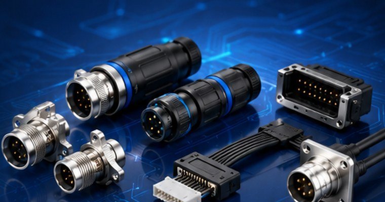
Vibration and shock
Motors, vehicles, industrial equipment and display modules may expose connectors to continuous vibration and impact.

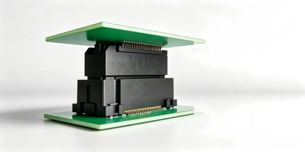
GSConn floating board-to-board connectors help absorb mounting tolerances, vibration, shock and mechanical stress, improving mating reliability in compact electronic systems.
In high-density PCB interconnection, vibration, pressure, mounting deviation and PCB deformation may damage the electrical interface or mechanical structure. A floating structure helps absorb these forces before they are transferred to contacts or solder joints.
Motors, vehicles, industrial equipment and display modules may expose connectors to continuous vibration and impact.
During automated assembly or blind mating, small positional deviations can generate stress on the mating interface.
Board warpage, installation error or long-term mechanical stress may affect mating reliability and solder durability.
A floating connector is a board-to-board connector with an internal floating structure. It provides standard electrical and mechanical connection performance while allowing limited relative movement during mating. This movement helps correct misalignment, absorb stress and reduce the risk of PCB damage.
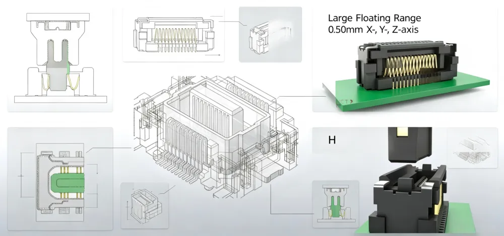
Absorbs misalignment and tolerance during PCB assembly and maintenance, helping reduce solder joint stress.
Helps reduce the influence of vibration and external shock, supporting stable connection in demanding environments.
In certain designs, floating board-to-board connectors may reduce the need for higher-cost flexible printed circuits.
Floating connectors are used in applications where vibration, shock, blind mating and assembly tolerance are common design challenges.

PLC, CNC equipment, sensor modules, control modules and industrial automation systems.

Reliable board-to-board interconnection for compact medical devices and high-stability electronic modules.

Compact board-to-board interconnection for consumer devices, smart equipment and vibration-sensitive electronic modules.
The following data is prepared for website presentation. Final specifications should follow official GSConn datasheets and drawings.
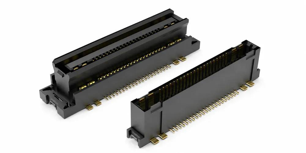
30Pin and 50Pin configurations with power pins and signal pins.
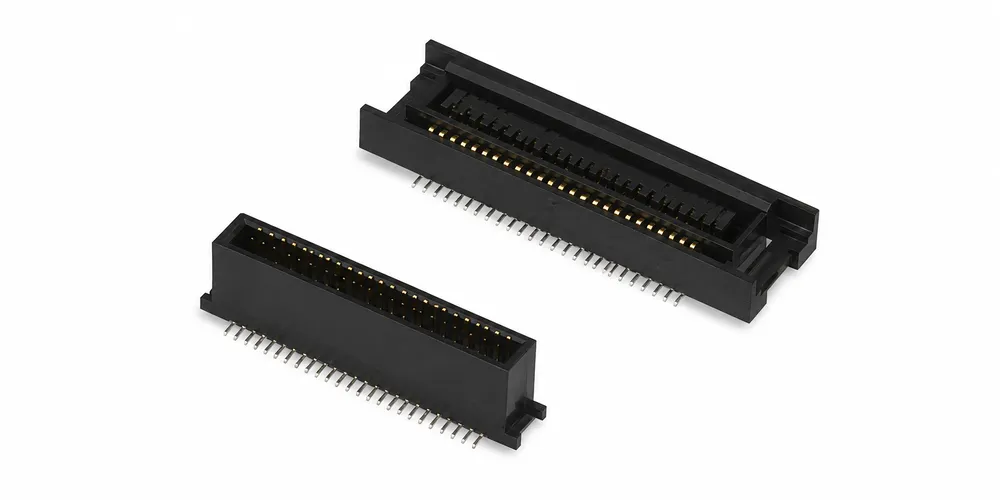
40Pin, 60Pin and 80Pin configurations for compact board-to-board interconnection.
| Item | Power + Signal Mixed Series | Signal Series |
|---|---|---|
| Pitch | 0.80mm | 0.80mm |
| Pin Count | 30Pin, 50Pin | 40Pin, 60Pin, 80Pin |
| Stacking Height | 8.00mm, 9.00mm, 11.75mm, 12.75mm | 8.00mm, 9.00mm, 11.75mm, 12.75mm |
| Rated Current | 5A for power pins, 0.5A Max. for signal pins | 0.5A Max. |
| Rated Voltage | AC / DC 50V Max. | AC / DC 50V Max. |
| Contact Resistance | 100mΩ Max. | 100mΩ Max. |
| Mating Cycles | 100 cycles | 100 cycles |
| Floating Range | X / Y / Z ±0.50mm | X / Y / Z ±0.50mm |
| Environmental | RoHS 2.0 + HF | RoHS 2.0 + HF |
| Packaging | Tape & Reel + Vacuum Packaging | Tape & Reel + Vacuum Packaging |
Note: Parameters are for website display only. Please refer to official datasheets, drawings and certification documents for final use.
Share your board spacing, pin count, current requirement, stacking height, floating range and application environment. GSConn can support product selection, samples and design-in evaluation.