
Stacked vs Side-by-Side USB Connector: PCB Layout and Signal-Integrity Comparison
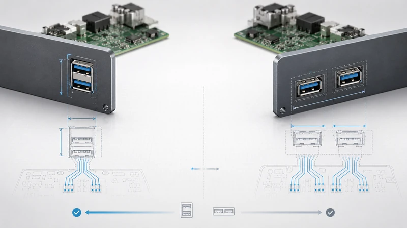
When a PCB needs two USB ports, the first decision is mechanical: put the ports vertically in one stacked connector, or place two connectors side by side. That choice affects panel width, enclosure height, signal routing, shielding, service access, and purchasing flexibility.
There is no universal winner. Stacked saves width; side-by-side buys margin.
Quick comparison
| Criteria | Stacked USB | Side-by-side USB |
|---|---|---|
| Panel width | Best | Uses more width. |
| Connector height | Taller | Lower profile. |
| Panel cutouts | Usually one | One wide opening or two openings. |
| USB 2.0 performance | Usually no concern | Usually no concern. |
| USB 3.x margin | More layout-sensitive | Easier to keep clean. |
| Mechanical stress | Higher at upper port | Lower leverage on PCB. |
| Rework and sourcing | More vendor-specific | Simpler and more flexible. |
| Sealing | One gasket area possible | More openings to manage. |
1. Mechanical footprint
A stacked connector puts two ports in a vertical column. This can roughly halve the width needed for the USB area, which is why it is attractive in 1U equipment, narrow industrial controllers, IoT gateways, and compact medical products.
Side-by-side connectors spread the ports horizontally. The layout is wider, but the connector height is lower, cable access is straightforward, and each port can use a common single-port footprint.
The real comparison should use the effective area, not just the connector body. Include cable overmold clearance, panel tolerance, ESD components, mounting holes, and any keep-out required for rework.
2. PCB routing differences
With side-by-side connectors, the two ports can usually be routed with similar breakout geometry. With stacked connectors, the upper port has additional internal routing through the connector body, and the escape pattern may be tighter.
For USB 2.0, this is normally easy to manage. For USB 3.x, it is more important to follow the recommended footprint and keep the SuperSpeed pairs short, referenced, and free of stubs.
A good stacked USB 3.x layout should:
- use a shielded connector;
- route 90 Ω differential pairs with a continuous reference plane;
- avoid unnecessary layer changes;
- place ESD parts close to the connector;
- use ground stitching around shell and shield connections;
- leave enough clearance from switching power components and antennas.
3. Signal-integrity comparison
Side-by-side connectors usually have the advantage at high speed because the ports are physically separated and the routing is more direct. Stacked connectors can still be suitable at 5 Gbps, but the connector choice and PCB layout carry more weight.
The difference becomes more important when the link already has little margin: long cables, marginal host controllers, noisy enclosures, low-cost cables, or high-temperature operation. In those cases, do not choose stacked until SI data or pre-compliance testing supports the decision.
For USB4 and other very high-speed Type-C designs, use connectors specifically designed and tested for that ecosystem. Do not extrapolate from a USB 3.0 Type-A stacked connector.
4. Enclosure and panel design
Stacked wins when the panel is crowded. One vertical cutout can leave valuable width for Ethernet, power, antennas, LEDs, or labels. It can also simplify sealing because the gasketed area is concentrated in one location.
Side-by-side wins when the product has more horizontal panel space than vertical clearance. It also gives more room for fingers and cable overmolds, which matters when the port is recessed or users connect cables frequently.
Before freezing the panel, check:
- cable overmold width and height;
- finger access to both ports;
- screw-lock or latch access if used;
- gasket compression and screw locations;
- whether one inserted cable blocks the other port.
5. Mechanical durability
The upper port of a stacked connector creates more leverage on the PCB during insertion and extraction. In equipment that is rarely touched, this may not matter. In field-service equipment, it can drive the mounting strategy.
Use side-by-side when frequent cable insertion is expected and the panel has space. Use stacked with reinforcement when panel width is tight but durability is still required. Reinforcement can be through-hole shell stakes, a metal bracket, a nearby PCB mounting screw, or a panel-mount connector.
6. Cost and supply
The connector unit price is only part of the cost. Stacked connectors can cost more as components, but they may reduce PCB width, panel machining, gasket count, and assembly time. Side-by-side connectors are often cheaper and easier to second-source, but they consume more layout space.
For a mature product, check three things before choosing stacked:
- Is there an approved alternate with the same footprint?
- Does the supplier offer the exact mounting and temperature version needed?
- Is the panel cutout tied to a vendor-specific geometry?
If second sourcing is a major purchasing requirement, side-by-side may be easier unless the stacked connector family is already qualified.
7. Which should you choose?
Choose stacked when panel width is the scarce resource, two ports need to appear in one service area, USB 2.0 is enough or USB 3.x has been validated, and the connector can be mechanically supported.
Choose side-by-side when high-speed margin, easy sourcing, low profile, frequent use, or high-current operation is more important than panel width.
Choose right-angle stacked when the enclosure strongly favors stacked geometry but the vertical-stacking tradeoffs are uncomfortable. Confirm availability early; right-angle variants are often more vendor-specific.
8. Example tradeoffs
A 1U server rear panel often chooses stacked USB even when the PCB has enough area, because the rear shield width is already crowded with RJ45, VGA, serial, and power-management connectors. In that case, the mechanical width saving is worth more than the marginal SI benefit of side-by-side ports.
A machine-vision controller may make the opposite decision. If the USB port is connected to a high-speed camera through a long cable, the cleaner routing and lower crosstalk of side-by-side connectors may matter more than saving 20 mm of panel width.
A medical cart can go either way. If the ports are mostly used for service and log export, stacked is tidy and easy to label. If nurses plug and unplug accessories many times a day, side-by-side or a reinforced panel-mount stacked connector is safer.
9. GSConn selection notes
GSConn stacked and side-by-side USB options should be specified by application constraints: USB generation, mounting style, shielding, operating temperature, sealing, retention method, and documentation needs. For USB 3.x or regulated equipment, request the recommended footprint and any available SI or qualification data before committing the PCB and panel.
FAQ
Does USB certification care whether the connector is stacked?
Certification and compliance depend on the electrical and mechanical performance of the specific connector or assembly, not just the visual form factor.
Is stacked always cheaper at product level?
No. It can reduce panel and PCB cost, but the connector may be more expensive and less flexible to source. Run the cost using your actual panel and board constraints.
Can stacked Type-C be used?
Yes, but Type-C designs are more sensitive to cable orientation, current rating, and high-speed requirements. Use a connector designed for the required USB/PD specification.
Which is better for industrial vibration?
Side-by-side has lower leverage, but a bracketed or panel-mounted stacked connector can perform well. The mounting strategy matters more than the visual arrangement.