
USB Connector for Energy Storage — BMS & Battery Monitoring
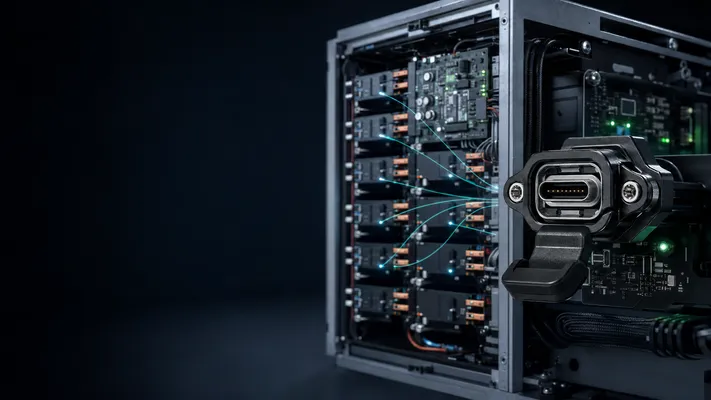
Quick Summary
| Parameter | Requirement |
|---|---|
| Temperature range | -30°C to +70°C (indoor BESS), -40°C to +85°C (outdoor container) |
| IP rating | IP54 minimum (indoor), IP65 (outdoor container) |
| USB function | BMS configuration, data logging, firmware update, CAN bus gateway |
| USB speed | USB 2.0 sufficient for BMS communication |
| Special requirements | High isolation (battery voltage to low-voltage side), wide temp cycling |
1. USB in Battery Energy Storage Systems (BESS)
Energy storage systems — from residential 10kWh wall units to utility-scale 100MWh containerized BESS — use USB for non-power-path functions:
| Function | USB Port | Location | Notes |
|---|---|---|---|
| BMS configuration (initial setup) | 1× Type-A or Type-C | Front panel / service door | USB-to-CAN or USB-to-RS485 interface |
| Data logging (cell voltages, temperatures, SOC) | 1× Type-A | Internal | USB flash drive or SSD |
| Firmware update (BMS, EMS, PCS) | 1× Type-A | Service port | OTG-capable USB controller |
| Remote monitoring gateway (4G/Modbus) | 1× Type-A | Internal | USB-to-4G modem dongle |
| HVAC controller (container BESS) | 1× Type-A | Internal | USB-to-RS485 for HVAC setpoint |
Two USB ports recommended: one service-accessible (configuration + firmware) and one internal (data logging + modem). Stacked USB connector fits both in minimal panel space.
Scope Clarification
In BESS, USB should be positioned accurately: USB is commonly used for commissioning, service access, data logging, or bridging to CAN/RS485, but critical real-time battery protection should remain on dedicated BMS communication and safety circuits. This distinction matters for engineering credibility and prevents the article from overstating USB’s role in safety-critical or real-time control paths.
2. Environmental Challenges
Indoor (Commercial / Industrial BESS)
| Condition | Value |
|---|---|
| Ambient | 15–35°C (air-conditioned battery room) |
| Enclosure internal | +10–20°C above ambient (battery heat + power electronics) |
| Humidity | 30–70% RH (controlled) |
| Dust | Low (filtered air) |
Requirement: Commercial temp (0–70°C) sufficient for indoor BESS. Standard USB 2.0 Type-A is adequate.
Outdoor (Containerized BESS)
| Condition | Value |
|---|---|
| Ambient (worst case) | -30°C to +50°C |
| Container internal | -20°C to +60°C (with HVAC) |
| Solar loading | +20°C on container roof |
| Humidity | 10–95% RH (uncontrolled) |
| Salt spray | Yes (coastal, offshore wind + BESS) |
| Thermal cycling | 20°C delta per day × 365 days/year × 15 years = 5,475 cycles |
Requirement: Industrial temp (-40°C to +85°C) minimum. IP65 for externally accessible ports. Conformal coating on PCB. LCP housing for thermal cycling stability.
3. BMS USB Interface: Technical Details
Battery Management Systems use USB for two distinct purposes:
USB-to-CAN / USB-to-RS485 Gateway
The BMS communicates internally via CAN bus (or RS485 for smaller systems). The service port converts USB to CAN for laptop connection:
| Parameter | Value |
|---|---|
| Protocol | USB CDC (virtual COM port) or USB HID |
| Data rate | 250 kbps–1 Mbps (CAN), 115200 bps (RS485) |
| USB speed | Full-speed (12Mbps) sufficient |
| Driver | FTDI (FT232R/FT4232H) or CP210x |
| Isolation | Galvanic isolation required between USB side and CAN side |
Isolation is critical. The USB port on a BMS connects to a laptop at ground potential. The CAN bus is on the battery side, which may float at hundreds of volts above ground. Without galvanic isolation, connecting a laptop could cause ground loops or shock hazard.
Solution: use isolated USB-to-CAN adapter (built into BMS PCB or external dongle). The USB connector itself is standard — isolation is on the PCB between the USB controller and the CAN transceiver.
USB Data Logging
BMS continuously logs cell voltages, temperatures, state of charge, and fault events. USB flash drive or SSD provides local storage:
| Parameter | Value |
|---|---|
| Log rate | 1–10 Hz (cell data), 100 Hz (fault capture) |
| Data volume | 50–500 MB/day (10 cells @ 1 Hz) |
| Storage device | USB 2.0 flash drive (32GB–256GB) or USB 3.0 SSD (1TB+) |
| USB speed | USB 2.0 (480Mbps) adequate for flash; USB 3.0 (5Gbps) for SSD |
4. Residential vs Utility-Scale BESS
| Factor | Residential (5–20 kWh) | Commercial (50–500 kWh) | Utility (1–100+ MWh) |
|---|---|---|---|
| USB ports | 1–2 | 2–3 | 3–4 |
| Access | Service door (end user visible) | Service panel (technician only) | Service panel (locked) |
| Temperature | Indoor, 15–35°C | Indoor or outdoor container | Outdoor container |
| USB connector | Standard Type-A | Industrial stacked | Industrial stacked + IP67 front panel |
| Locking | No | Optional | Recommended |
| Life expectancy | 10 years | 15 years | 20+ years |
| Mating cycles | <500 | <1,000 | <2,000 (quarterly service) |
5. Special Considerations for BESS
High-Voltage Isolation
Battery stacks in utility BESS reach 1,500V DC (1,500V systems are the new standard, replacing 1,000V). Any externally accessible connector typically should maintain creepage/clearance per IEC 60664.
USB connectors themselves don’t handle isolation — isolation is on the PCB. But the USB connector’s mechanical design (panel-mount with grounded shell) should prevent accidental contact between the USB shield and battery-side circuitry.
Thermal Cycling
Containerized BESS in desert environments: daytime +50°C internal, nighttime +15°C internal — 35°C diurnal cycle. Over 15 years, USB connector solder joints and housing material see 5,000+ thermal cycles.
Recommendation: Through-hole mounting (not SMT) for internal USB connectors. LCP housing (CTE 8–15 ppm/°C, close to FR4 at 16–18 ppm/°C) for minimal CTE mismatch at solder joints.
Fire Safety
Lithium-ion BESS fire risk is well-documented. All plastic components including USB connectors typically should be UL 94 V-0. LCP and PPS both achieve V-0 without halogenated flame retardants.
6. GSConn BESS Recommendations
| BESS Type | USB Configuration | GSConn Part |
|---|---|---|
| Residential | 2× USB 2.0 Type-A, SMT | Standard stacked USB 2.0 |
| Commercial indoor | 3× USB 2.0 (2 stacking + 1 single) | Industrial stacked USB 2.0 + single |
| Commercial outdoor | 2× USB 2.0 internal + 1× IP65 front panel | Industrial stacked + IP65 panel-mount |
| Utility container | 2× USB 2.0 internal, 2× IP67 service panel | Industrial stacked ×2 + IP67 panel-mount |
| All outdoor | LCP housing, 1.0µ” gold, through-hole | Industrial stacked USB (full spec) |
GSConn industrial stacked USB connectors meet the temperature cycling, isolation, and longevity requirements of energy storage systems. IP67 panel-mount versions available for outdoor containerized BESS service ports. For high-voltage isolation requirements, GSConn can provide connectors with grounded metal shell and specified creepage distances — contact engineering for BESS-specific part numbers.
Related reading:
– Wide Temperature Stacked Connector
– Industrial USB Connector Guide
– How to Choose USB Connector
Technical References for Editorial Review
This article was reviewed for engineering accuracy against commonly used connector and USB ecosystem references, including USB-IF Type-C / USB4 / USB Power Delivery documentation, IEC 60512 connector test methods, EIA-364 test methods, and representative connector manufacturer datasheets. Always verify final dimensions, plating thickness, reflow limits, and durability ratings against the exact connector datasheet before releasing a design.