
Server Backplane Connectors: A Practical Selection Guide
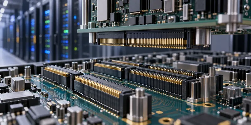
Choosing a server backplane connector begins with the system interface, not a headline data rate. Drive form factor, PCIe generation, lane count, power delivery and chassis alignment all affect the decision. The connector must work within the complete channel and the mechanical assembly.
A useful specification identifies the exact mating interface first, then allocates electrical and mechanical requirements to each component.
Separate the application from the connector family
| Application | Establish first | Evaluate next |
|---|---|---|
| SAS or SATA storage | Drive interface, connector standard and supported protocol | Routing, hot-plug requirements and drive alignment |
| NVMe storage | Drive form factor and physical interface | PCIe channel, power, management and cooling |
| Expansion or accelerator card | Slot or mezzanine interface, lane count and generation | Channel loss, retention and service clearance |
| Power distribution | Bus voltage, continuous load and fault conditions | Temperature rise, sequencing and conductor sizing |
NVMe is a storage protocol; its version is not a direct label for PCIe generation. Specify the actual PCIe capability of the drive and host. Likewise, a generic board-to-board connector is not automatically a standardized storage-drive interface.
Use the correct speed units
PCIe Gen3, Gen4 and Gen5 operate at 8, 16 and 32 GT/s respectively per lane. GT/s describes transfers, while usable payload throughput also depends on encoding and protocol overhead. State the generation, lane count and direction when comparing bandwidth. See the PCI-SIG specifications overview.
For a connector advertised by a data rate, ask how it was evaluated: signaling format, channel length, launch geometry and acceptance criteria matter. A connector data-rate headline is not evidence that the entire server channel meets a particular PCIe requirement.
Evaluate the complete signal path
Include PCB traces, vias, connectors, cables where present and transmitter/receiver behavior in the channel model. Request a suitable S-parameter model for the selected connector configuration and understand its reference planes. Check insertion loss, return loss and crosstalk against the applicable interface budget.
Do not apply one universal connector loss limit to every generation. Via back-drilling, improved laminates, shorter routing or a different interconnect architecture may help, but the model should identify which change is needed. Account for manufacturing tolerances and simultaneous aggressor activity rather than validating an ideal isolated lane only.
Design for blind mating and service
Check guide features, float, insertion force and chassis tolerance accumulation. The connector should not be expected to absorb unlimited misalignment or carry structural loads intended for the chassis. Confirm the fully mated position and retention method with production-representative parts.
For serviceable equipment, specify expected mating cycles, handling access and replacement procedures. Where hot plugging is required, verify contact sequencing, power control and system behavior together. Staggered contacts alone do not make an assembly safe to connect under load.
Validate power at the installed temperature
Power-contact capability depends on wire or PCB copper, adjacent loaded contacts, airflow and contact resistance. Test the worst realistic loading pattern in the enclosure. Include both supply and return paths and review whether signal-connector placement restricts cooling.
FAQ
Can a connector upgrade make a Gen4 design support Gen5?
Not by itself. The host, endpoint, PCB channel and all interconnects must support the intended generation.
Which qualification data should I request?
Ask for drawings, mating specifications, channel models, thermal data and durability evidence for the exact configuration being considered.
Prepare the selection package
Send GSConn the interface definition, lane count, stack height, mechanical envelope, power load and target channel requirements. Request candidate-specific evidence before treating any suggested series as approved for the server design.