
Telecom Connector Selection: RF, Fiber, Data and Power
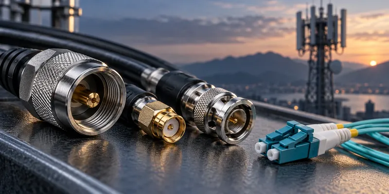
Communication equipment uses several different interconnect systems. RF connectors carry radio-frequency signals, optical interfaces connect fiber links, high-speed board connectors support internal electronics, and power connectors feed the equipment. Their requirements cannot be reduced to one bandwidth or environmental rating.
Map each connection in the actual architecture before selecting parts. Radio and baseband functions may be integrated or distributed, so a single base-station diagram will not describe every installation.
Match the connector to its role
| Connection | Candidate interface | Key selection questions |
|---|---|---|
| External RF feeder | 4.3-10, N-type or another specified coaxial interface | Frequency, power, return loss and PIM |
| Optical link | LC, MPO or another defined optical interface | Fiber type, polish, polarity and optical budget |
| Internal high-speed data | Board-to-board or cable interconnect | Lane rate, signaling format and channel loss |
| Equipment power | Power connector or busbar connection | Current, voltage drop, temperature rise and protection |
| Outdoor service interface | Sealed electrical or optical assembly | Ingress conditions, installation and service access |
Connector families contain different constructions and ratings. Always evaluate the selected part and cable combination.
Specify RF performance with test conditions
Passive intermodulation, or PIM, can arise from nonlinear junctions in an RF path. Contact condition, contamination, material choices and assembly quality can influence it. Low-PIM performance is therefore an assembly requirement as well as a connector consideration.
A PIM value without test conditions is incomplete. State carrier frequencies, input power, measured intermodulation order, acceptance level and whether mechanical stress is applied. There is no single PIM threshold appropriate to every base station.
The 4.3-10 family is one established option for mobile communication interconnects. Compare the selected assembly’s RF performance, coupling method and installation envelope with the system requirements. Do not treat a family-level frequency claim as proof of the assembled cable’s performance.
Separate optical connectors from data-rate claims
An LC or MPO interface alone does not establish link speed. The transceiver, fiber, wavelength, lane arrangement, connector losses and link length determine suitability. Specify single-mode or multimode fiber, the polish type and the required polarity. Do not mate incompatible polish types.
A transceiver cage is also not the complete link. Review the associated electrical connector, module format, PCB layout and thermal management. Confirm that the host implementation and module support the required interface.
Check outdoor installation details
Define exposure to rain, dust, salt, UV, temperature cycling and service handling. Request the ingress rating for the installed condition, including panel seals, cable glands and protective caps. An unmated connector may require a cap even when its mated assembly carries an outdoor rating.
Allow access for the specified coupling method and assembly tools. Route cables to avoid persistent loads on the connector, maintain bend radius and provide appropriate strain relief. Follow the manufacturer’s cleaning and coupling instructions for both RF and optical interfaces.
Validate power and data together
Use the actual load profile and local enclosure temperature for power-contact evaluation. Nearby heat sources and cable bundling can change the result. For data paths, validate the complete channel and account for interference from neighboring electronics.
FAQ
Does an IP67 rating establish suitability for every outdoor site?
No. Corrosion, UV, chemicals, installation condition and long-term temperature exposure need separate review.
Does a connector family name determine its frequency limit?
No. Use the selected part’s datasheet and the assembly’s measured performance.
Prepare a telecom connector enquiry
Send GSConn the interface list, RF and optical requirements, lane configuration, power load and environmental conditions. Request candidate-specific documentation for each connection rather than one general “5G connector” specification.