
Cable Assembly Best Practices: Crimping, Shielding and Tests
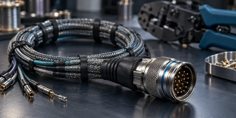
A reliable cable assembly depends on how the wire, terminal, housing and strain relief work together. Good components can still fail when preparation, tooling or routing is inconsistent. The most effective improvements make the assembly process repeatable and its acceptance criteria measurable.
Define the build requirements before selecting a test voltage or an overmold. Different cable constructions and end equipment require different controls.
Release a complete assembly drawing
Specify connector and terminal part numbers, wire construction, conductor size, cable length tolerances and the pin-to-pin map. Include shield connections, twisted-pair assignments, labels, seal requirements and orientation views. Clearly identify whether connector views show the mating face or wire-entry side.
List the applicable workmanship requirements and revision. A sample harness is useful for fit checks, but it should not be the only production reference.
Control wire preparation and crimping
Use the terminal manufacturer’s strip length and tooling specification. There is no universal strip-length tolerance suitable for every terminal. Inspect for damaged strands, insulation trapped in the conductor crimp and exposed conductors outside the intended area.
A validated crimp process combines the correct wire-terminal-tool combination with dimensional inspection and mechanical testing. Crimp height and pull force answer different questions; passing one does not establish every aspect of crimp quality. Use cross-section evaluation where the qualification plan requires it.
Do not pre-tin a conductor intended for a crimp connection unless the terminal manufacturer specifically allows the process. Solder wicking and changes to the conductor bundle can affect the joint. Likewise, use ferrules only where the terminal system accepts them.
Give cable loads a mechanical path
| Strain-relief method | Evaluate before selection |
|---|---|
| Clamp or cable gland | Cable diameter range, grip and jacket damage |
| Molded boot | Bend transition and flexibility over temperature |
| Overmold | Adhesion, material compatibility, process pressure and repairability |
| Backshell | Retention, shielding continuity and installation access |
| Internal tie-down | Load transfer without crushing or sharply bending the cable |
An overmold is not automatically the best solution. It must work with the jacket material, cable movement and service requirements. Check that pulling or bending the cable does not transfer damaging loads to individual terminals or solder joints.
Design shielding for the interference problem
For high-frequency shielding, a short, low-impedance connection around the cable shield can be valuable. A long drain-wire pigtail adds inductance and may reduce performance. However, shield bonding must follow the system’s EMC and grounding design; one termination rule will not solve every application.
Maintain the intended shield coverage through the connector and backshell. Review both ends of the cable and how the shield connects to the enclosure. Confirm performance in the assembled system rather than declaring a shield “complete” from its appearance.
Define production and qualification tests separately
| Test | Typical purpose | Plan detail to define |
|---|---|---|
| Continuity and miswire check | Verify the wiring map | Nets, limits and test coverage |
| Short-circuit check | Find unintended connections | Shield and unused-contact treatment |
| Insulation resistance | Evaluate insulation leakage | Voltage, duration and acceptance limit |
| Dielectric withstand | Evaluate specified insulation strength | Approved voltage, ramp, duration and leakage limit |
| Pull, flex and environmental tests | Qualify durability | Samples, loads, cycles and failure criteria |
For passive harnesses, complete continuity and miswire checks are often useful production controls. Do not apply a generic 500–1,000 V withstand test to every assembly. Connected electronics and protective components may require a different procedure or exclusion from that test.
FAQ
Does continuity prove a crimp is reliable?
No. A weak joint may initially conduct. Mechanical quality and durability require separate evidence.
How far apart should cable supports be?
Use cable mass, motion, vibration and bend-radius requirements to determine support spacing; a fixed interval is not universal.
Prepare a cable assembly enquiry
Send GSConn the drawing, wire specification, operating environment, annual quantity and inspection plan. Ask for confirmation of tooling, strain-relief design and test coverage before approving samples for production.