
Low Profile & Short Body USB Connector — Compact Design Selection
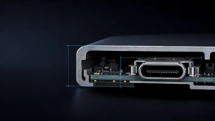
Quick Decision Matrix
| Connector Type | Height Above PCB | Body Length (mating face to rear) | Saves vs Standard | Best For |
|---|---|---|---|---|
| Standard Type-A | 6.9mm | 14.5mm | — | Desktop, server |
| Low-profile Type-A | 4.0–5.0mm | 14.5mm | 28–42% height | Thin laptops, USB hubs |
| Short-body Type-A | 6.9mm | 9.5–12.0mm | 17–34% length | Compact front panel, tight enclosures |
| Mid-mount Type-C | 2.8mm above + 2.8mm below | 10.5mm | 55% height | Smartphones, tablets |
| Low-profile Type-C | 4.8mm | 10.5mm | 30% height | Ultrabooks, thin tablets |
| Ultra-short-body Type-C | 6.5mm | 7.5mm | 28% length | Extremely tight board edge |
1. When Z-Height Is the Problem: Low-Profile
Standard USB Type-A rises 6.9mm above PCB. For thin devices, that 6.9mm can be the difference between “fits” and “redesign with a daughterboard.”
Low-Profile Type-A
| Parameter | Standard | Low-Profile |
|---|---|---|
| Height above PCB | 6.9mm | 4.0–5.0mm |
| Panel cutout | 14.5 × 7.0mm | Same |
| Interior shell height | Unchanged | Reduced, tighter cable fit |
| Mating | Standard cable, no issue | Standard cable, slightly tighter |
| Durability | 10,000 cycles | 5,000–8,000 cycles (thinner shell) |
Trade-off: low-profile saves 2mm in Z-height but reduces shell rigidity. Not for high-cycle or high-vibration applications.
Low-Profile Type-C
| Parameter | Standard Type-C | Low-Profile Type-C |
|---|---|---|
| Height (connector body) | 6.5mm | 4.8mm |
| Typical PCB footprint | about 10–11 × 7–8mm | about 10–11 × 7–8mm (unchanged) |
| Mating | Standard Type-C cable | Standard Type-C cable |
| Current rating | 5A (PD) | 3A (reduced contact area) |
Low-profile Type-C is common in ultrabooks (MacBook Air, Dell XPS) where the total device thickness is 11–15mm and the connector typically should not protrude.
2. When Board Depth Matters: Short-Body
Short-body connectors reduce the distance from the mating face to the rear of the connector. This is critical when PCB edge space is at a premium or the connector is mounted near a wall.
Short-Body Type-A
| Parameter | Standard | Short-Body |
|---|---|---|
| Body length (face to rear) | 14.5mm | 9.5–12.0mm |
| Height | 6.9mm | 6.9mm (unchanged) |
| Solder tail arrangement | Standard (2-row) | Compact (single-row or folded) |
| PCB real estate saved | — | 2.5–5.0mm |
Use case: A 1U server front panel with multiple USB ports side-by-side. Standard connectors need 14.5mm depth per port; stacked side-by-side with short-body connectors can fit 3 ports in 3 × 9.5mm = 28.5mm instead of 3 × 14.5mm = 43.5mm.
Ultra-Short-Body Type-C
| Parameter | Standard Type-C | Ultra-Short |
|---|---|---|
| Body length | 10.5mm | 7.5mm |
| Solder tabs | 2 × 12 (24 total) | 2 × 12 (24 total, tighter pitch) |
| Reflow challenge | Standard | Higher (tighter pads, more alignment critical) |
Use case: Board-edge mounting where PCB extends only 3–5mm beyond connector front face. Common in compact IoT gateways and embedded systems.
3. Board-Edge Connectors: When the Connector Hangs Over
Board-edge USB connectors mount such that part of the connector body extends beyond the PCB edge. This saves PCB real estate but requires:
- PCB outline: Cutout around connector body, leaving only solder tabs on PCB
- Panel alignment: Connector front face typically should align with enclosure panel — tolerance ±0.2mm
- Strain relief: No PCB under connector body means more stress on solder tabs during insertion
| Board-Edge Type | PCB Inboard | Overhangs | Assembly |
|---|---|---|---|
| Full inboard (standard) | 100% | 0% | Standard SMT reflow |
| Partial overhang | 70% | 30% | Requires support fixture in reflow |
| Full overhang (board-edge) | 50% | 50% | Requires support fixture + panel alignment |
4. Mid-Mount: The Thinnest Possible
Mid-mount USB connectors embed into a PCB cutout, accessible from both sides. Used in smartphones and tablets where total device thickness is 6–8mm.
| Connector Type | Total Height (above + below) | PCB Thickness | Assembly |
|---|---|---|---|
| Mid-mount Type-C | varies by series | 0.8–1.0mm | Dual-side reflow |
| Mid-mount micro USB | 4.0mm | 0.8–1.0mm | Dual-side reflow |
Assembly note: Mid-mount connectors are placed in the PCB cutout before reflow. The PCB typically should be supported on both sides during reflow, and the connector typically should not shift during the liquid phase (solder surface tension usually centers it, but fixture backup is recommended).
5. Comparison Table: All Compact Options
| Type | Height Saved | Length Saved | Mating Cycles | Complexity | Cost Premium |
|---|---|---|---|---|---|
| Low-profile Type-A | 28–42% | 0% | 8,000 | Low | +15–25% |
| Short-body Type-A | 0% | 17–34% | 10,000 | Low | +10–20% |
| Low-profile Type-C | 26% | 0% | 10,000 | Low | +10–15% |
| Ultra-short Type-C | 0% | 29% | 5,000 | Medium | +25–35% |
| Mid-mount Type-C | 55% | 0% | 10,000 | High | +30–50% |
Datasheet First: Dimension Caveat
The dimensions in this guide are typical design envelopes for comparison only. USB connector mechanical size is not fully defined by the USB protocol name. Shell length, solder-tab position, mid-mount depth, board-lock geometry, peg diameter, and panel datum vary by manufacturer and series. Always design the PCB footprint and enclosure cutout from the exact 2D drawing / 3D model of the selected connector.
6. Selection Flow
Need compact USB?
├── Height constraint
│   ├── <5mm total → Mid-mount Type-C (on PCB cutout)
│   ├── 5–7mm → Low-profile Type-C (4.8mm)
│   └── >7mm → Standard Type-C or Type-A
│
├── Depth constraint (PCB edge)
│   ├── <8mm behind face → Ultra-short-body Type-C
│   ├── 8–12mm → Short-body Type-A or standard Type-C
│   └── >12mm → Standard (no constraint)
│
├── Both constrained → Mid-mount + short-body combination (custom)
│
└── No constraint → Standard (cheapest, most reliable)
7. GSConn Compact USB Series
| Type | Height | Body Length | Mounting | Features |
|---|---|---|---|---|
| Low-profile Type-A | 4.5mm | 14.5mm | SMT | 8,000 cycles |
| Short-body Type-A | 6.9mm | 9.5mm | Through-hole | 10,000 cycles |
| Low-profile Type-C | 4.8mm | 10.5mm | SMT | 10,000 cycles, 5A |
| Ultra-short Type-C | 6.5mm | 7.5mm | SMT | 5,000 cycles |
| Mid-mount Type-C | varies by series total | 10.5mm | Dual SMT | 10,000 cycles, dual-sided |
GSConn compact USB connectors save up to 55% in height and 34% in depth versus standard connectors. Low-profile, short-body, and mid-mount variants available for USB Type-A and Type-C. For designs where both height and depth are constrained, contact GSConn engineering for custom hybrid solutions.
Related reading:
– Vertical USB Type-C Connector Guide
– USB Connector PCB Layout Guide
– How to Choose USB Connector
Technical References for Editorial Review
This article was reviewed for engineering accuracy against commonly used connector and USB ecosystem references, including USB-IF Type-C / USB4 / USB Power Delivery documentation, IEC 60512 connector test methods, EIA-364 test methods, and representative connector manufacturer datasheets. Always verify final dimensions, plating thickness, reflow limits, and durability ratings against the exact connector datasheet before releasing a design.