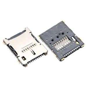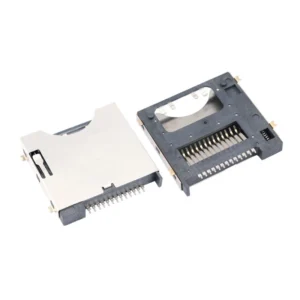
microSD Socket Selection for Edge AI Devices: Sustained Write, Heat and Retention

Edge AI changes the load profile, and the socket was not specified for it
A camera writes a photo and stops. A dashcam writes in bursts and then idles. An edge AI device writes continuously — sensor logs, video rings, inference traces — for as long as it is powered. That difference turns three socket parameters from background details into design constraints: sustained thermal behaviour, retention in a fanless enclosure, and the card-detect path.
This article covers what changes when the write load becomes continuous, and how to choose a microSD socket for that regime rather than for the burst-write regime the socket was originally characterised in.
Continuous write versus burst write
| Characteristic | Burst write (camera, dashcam) | Sustained write (edge AI, logger) |
|---|---|---|
| Duty cycle | Low — seconds per minute | High — most of the time |
| Card temperature | Rises then falls; averages low | Reaches steady state; averages high |
| Throttling | Rarely reached | Commonly reached |
| Socket thermal role | Irrelevant | A real part of the thermal path |
| Retention risk | Handling only | Handling plus continuous vibration |
The thermal point is the one that changes the socket choice. In a burst-write device, the card is cooled by the gaps between writes. In a continuous-write device, it reaches a steady temperature set by the balance between write power and the thermal resistance from the card to ambient.
The thermal path, from card to ambient
Heat leaves a microSD card by four routes, and the socket is involved in three of them.
| Path | Contribution | Socket influence |
|---|---|---|
| Card body to air | Small in still air | None |
| Card to socket shell | Moderate | Shell material and contact area |
| Shell to PCB | Significant | Solder tab area and ground plane connection |
| Through the electrical contacts | Moderate | Contact count, area, and resistance |
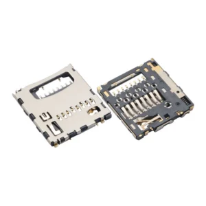
A stamped metal shell conducts better than a moulded plastic body, and a shell with large solder tabs transfers more heat into the board than one with small tabs. The PCB then acts as the heatsink, which is why ground plane design under the socket matters as much as the socket itself.
In a fanless sealed enclosure, there is no convective path to outside air. The board is the only heatsink, and the enclosure wall is the only path out. That makes the socket-to-board thermal resistance the dominant term, and a low-profile socket with minimal shell area the worst choice.
Why low-profile is a thermal trade-off
| Profile | Shell surface area | Thermal behaviour | Contact travel |
|---|---|---|---|
| 1.28 mm | Smallest | Poorest conduction to the board | Least — narrow card thickness tolerance |
| 1.5 mm | Moderate | Good balance | Moderate |
| 1.85 mm | Largest of the low-profile group | Best of the compact options | Most — widest tolerance |
| Hinged metal cover, 2.5 mm+ | Largest | Best overall, plus mechanical clamping | Widest |
The 1.28 mm socket exists to fit under a battery. In a device with a battery, the thermal problem is usually already solved by the fact that the battery needs a thermal budget of its own, and the card is a smaller heat source.
In a fanless edge device with no battery and no airflow, the 1.28 mm choice buys 0.2 mm of height and costs thermal headroom. If the design has the space, take the taller socket.
What throttling looks like, and why it is mistaken for a socket fault
SD cards reduce their write speed when the internal temperature exceeds a threshold set by the card vendor. The threshold varies by product, but it is typically in the range where the card is uncomfortable to touch.
The observable behaviour is a device that writes at full speed for a few minutes, then drops to a fraction of that, then recovers when idle. Because the socket is the thermal interface, the first suspicion is often the socket or the contacts.
| Symptom | Likely cause | How to confirm |
|---|---|---|
| Speed drops after minutes of writing | Card thermal throttling | Log card temperature, or repeat with the enclosure open |
| Speed drops immediately | Bus or controller limit | Check negotiated mode; compare with a bench card |
| Random write errors under load | Contact resistance or supply sag | Measure VCC at the socket under load |
| Card not detected after warm-up | Contact or solder joint expansion | Reflow inspection; thermal cycle the unit |
The third and fourth rows are genuine socket problems. The first is not, and changing the socket will not fix it — only reducing the thermal resistance or the write load will.
Retention in a fanless enclosure
Edge AI devices often live in two places: on a machine (vibration) or in an outdoor cabinet (thermal cycling). Both stress retention, and neither has a user who checks the card.
| Environment | Retention requirement | Mechanism |
|---|---|---|
| Machine-mounted, continuous vibration | Clamped or latched | Hinged metal cover, or push-push with a tested latch |
| Outdoor cabinet, thermal cycling | Clamped | Hinged cover; latch springs relax over cycles |
| Indoor rack, still air | Friction or latch acceptable | Push-push |
| Sealed IP67 housing | Tray | Tray with a replaceable gasket |
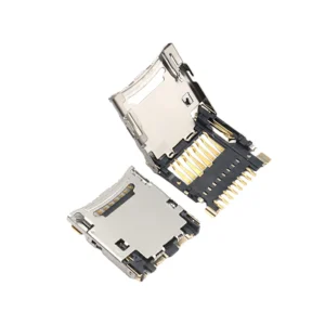
A hinged metal cover does double duty here: it clamps the card against vibration and it adds thermal mass and contact area. In a continuous-write application that combination is worth more than the height it costs.
Card detect and power-loss behaviour
An edge device that logs continuously should not be writing when the card is removed. Card detect lets firmware close the file system and flush before the card leaves.
Without a detect switch, removal during a write typically corrupts the file system. On a device deployed in the field with no console, that means a card that has to be reformatted on site — and if the device is remote, a visit.
| Requirement | Why it matters for edge AI |
|---|---|
| Card detect switch | Allows orderly close before removal |
| Write-protect switch (if used) | Prevents writes during service |
| Power-loss detection | Flush on brownout, not only on card removal |
| File system choice | Journaling reduces corruption risk at the cost of write amplification |
The last row is a design decision with a thermal consequence: write amplification means more writes for the same data, which means more heat. A journaling file system on a continuously writing device increases the thermal load.
Selection matrix for continuous-write devices
| Priority | Socket characteristic | Target |
|---|---|---|
| Thermal | Metal shell, large solder tabs | Low thermal resistance to the ground plane |
| Thermal | Profile | 1.5 mm or taller where space allows |
| Retention | Clamping mechanism | Hinged cover for machine-mounted or outdoor |
| Integrity | Card detect | Switch present and wired to an interrupt |
| Electrical | Contact plating | Stated gold thickness; sustained current through VCC |
| Mechanical | Insertion cycle rating | Low requirement — the card is rarely removed |
Note the last row. In a continuous-write device the card is often fitted once and sealed in. Cycle rating, which dominates consumer socket selection, is almost irrelevant. The requirements invert: thermal and retention matter, insertion convenience does not.
FAQ
Why does write speed drop after a few minutes? Card thermal throttling. The card protects itself when its internal temperature rises. Confirm by logging temperature or by repeating the test with the enclosure open.
Will a better socket stop throttling? It will reduce it, by lowering thermal resistance to the board. It will not eliminate it if the enclosure cannot reject the heat.
Is 1.28 mm suitable for a continuous-write device? Only if the thermal budget has been analysed. It has the least shell area and the poorest path to the board of the low-profile options.
Do I need card detect if the card is never removed? For a sealed device, not for removal — but for power-loss handling and for diagnosing a card that has failed in service, it is still useful.
Should I use a hinged cover in a fanless enclosure? If the device is machine-mounted or outdoors, yes. It clamps against vibration and increases the thermal contact area at the same time.
Does a taller socket really run cooler? It has more shell area and usually larger solder tabs, so it conducts more heat into the board. In a board-as-heatsink design that is the mechanism that matters.
Micro SD / TF Card Connectors for this design
View all 44 parts →