
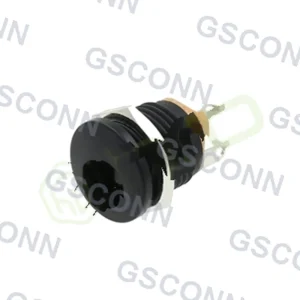
Right-Angle vs Vertical DC Jack Mounting: Solder Joint Load Paths

A heavier plug, a longer lever
A DC barrel plug is not a headphone plug. It is 9.5 to 11 mm long, it weighs several grams, and it is attached to a cable that is often thick and stiff. Insertion force can be 10 to 30 N, and extraction force is similar.
All of that load has to go somewhere, and where it goes depends on whether the jack is right-angle or vertical. The two mounting styles put the stress into different parts of the joint, and they fail differently.
The two orientations
| Orientation | Body position | Barrel direction | Typical use |
|---|---|---|---|
| Right-angle | Lies along the board | Parallel to the board, facing the case side | Compact equipment, low-profile enclosures |
| Vertical | Stands on the board | Perpendicular, pointing up | Board-top access, taller enclosures |
The right-angle part is popular because it keeps the jack low and lets the barrel reach a case opening on the side. The vertical part is simpler mechanically but demands headroom.
How the load resolves
Consider a force applied along the plug axis — the insertion push, or a cable being pulled.
| Orientation | Force direction relative to the board | What the joints see |
|---|---|---|
| Right-angle | Parallel to the board, at some height above it | Bending moment in the plane of the board, plus peel at the pads |
| Vertical | Perpendicular to the board, along the jack axis | Direct tension or compression on the pins |
This is the key difference. A vertical jack pushed straight down loads its pins in compression, which solder handles reasonably well. A right-angle jack pushed sideways creates a moment that tries to peel the pads off the board — a much worse loading mode for a surface-mount joint.
Add a hanging cable and the right-angle case gets worse: the cable weight acts downward, perpendicular to the insertion axis, creating a second moment that the vertical jack does not experience at all.
Solder joint loading compared
| Load case | Right-angle SMT | Right-angle through-hole | Vertical SMT | Vertical through-hole |
|---|---|---|---|---|
| Insertion push | Peel at pads | Shear in pins | Compression | Compression |
| Extraction pull | Reverse peel | Reverse shear | Tension | Tension |
| Hanging cable | Peel plus torsion | Shear plus torsion | Bending of pins | Bending of pins |
| Cable side pull | Worst case: combined moment | Shear and bending | Pin bending | Pin bending |
| Overall ranking | Weakest | Good | Good | Best |
Through-hole is substantially better than surface-mount in every case, because a pin in a plated hole resists shear and bending along its length rather than relying on a pad’s adhesion to the laminate.
Why SMT right-angle jacks fail
The failure is a fatigue crack, and it starts at the pad-to-solder interface on the side that sees tension.
| Stage | What happens | Observable symptom |
|---|---|---|
| 1 | Repeated peeling flexes the solder fillet | Nothing yet |
| 2 | A micro-crack forms at the fillet root | Nothing; resistance unchanged |
| 3 | The crack grows through the joint | Intermittent power when the cable moves |
| 4 | The joint opens under load | Device resets or shuts down |
| 5 | Arcing across the crack | Heat, discolouration, eventual open circuit |
Stage 3 is where the product starts behaving unpredictably, and stage 5 is where it becomes a fire risk rather than a reliability issue. The intermediate stages can last months.
The diagnostic signature
| Symptom | Cracked joint? | Alternative cause |
|---|---|---|
| Resets when the cable is moved | Yes | Worn barrel contact |
| Works when the jack is pressed toward the board | Yes — classic | — |
| Works cold, fails warm | Yes — differential expansion | Thermal issue elsewhere |
| Fails immediately when plugged in | No | Wrong supply, wrong polarity |
| Jack body hot at the pin | Possibly | Contact resistance |
The second row is the one to teach service technicians. Pressure restoring function is a mechanical joint failure, not a firmware or supply problem.
Design rules by orientation
| Requirement | Right-angle | Vertical |
|---|---|---|
| Mounting technology | Through-hole strongly preferred | SMT acceptable for light use |
| Board support | Rigid support directly behind the jack | Support under the jack footprint |
| Mechanical anchor | Anchor pins or a bracket | Anchor pins if the cable is heavy |
| Enclosure interface | Case must constrain the body, not just surround it | Case must resist side load on the barrel |
| Insertion cycles | Through-hole if more than a few hundred | SMT acceptable to a few hundred |
| Cable weight | Assume it will be hung; design for it | Bending of the pins is the risk |
When to add mechanical support
Support is not always necessary, but the threshold is lower than most designs assume.
| Condition | Support needed? |
|---|---|
| Plugged in once at installation, light cable | No |
| Plugged occasionally, cable rests on a surface | Marginal; through-hole preferred |
| Cable hangs from the jack | Yes |
| Plugged daily | Yes |
| Portable equipment carried by the cable | Yes, and consider a locking jack |
| Vibration present | Yes |
The third row is the one that gets missed. A power supply brick sitting on the floor with a cable hanging from a right-angle SMT jack applies a continuous peeling load, twenty-four hours a day, for years. The joint does not need to be cycled to fatigue.
Board-level measures
| Measure | Effect | Cost |
|---|---|---|
| Through-hole jack instead of SMT | Largest single improvement | Assembly step, board space |
| Anchor pins soldered to a pad | Resists peel | Requires a jack with anchors |
| Extra copper around the pads | Spreads load, delays pad lift | Board area |
| Standoff or bracket | Transfers load to the chassis | Extra part |
| Stiffener behind the jack | Reduces board flex | Board cost |
Extra copper around the pads is the cheapest measure and is frequently free — a slightly larger pad and a short teardrop costs nothing and meaningfully delays pad lift.
FAQ
Is right-angle weaker than vertical? For surface-mount joints, yes, because the load becomes a peeling moment rather than compression. Through-hole right-angle is fine.
Why does my device reset when I move the power cable? Most likely a cracked solder joint on the jack, especially on a right-angle SMT part with a hanging cable.
Will a heavier cable damage the jack? It loads the joint continuously even without cycling. If the cable hangs, design for it.
Can I use SMT for a jack that is plugged daily? Not advisable. Use through-hole or add a bracket that takes the load into the chassis.
What is the cheapest improvement? Larger pads with teardrops, and through-hole instead of SMT if the design allows it.
How do I confirm a cracked joint? Flex the board or press the jack toward the board while monitoring the supply rail. If the rail recovers, the joint is cracked.
DC Jack Connectors for this design
View all 116 parts →


