
Vertical USB Type-C Connector — Upright Mount Selection Guide
Quick Decision Matrix
| Orientation | PCB Footprint | Panel Access | Best For |
|---|---|---|---|
| Horizontal (standard) | about 10–11 × 7–8mm, face parallel to PCB | Side panel | Thin laptops, docks, side-access enclosures |
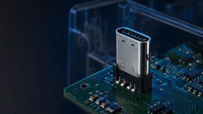
| Vertical (upright) | about 10–11 × 3–4mm, face perpendicular to PCB | Top or bottom panel | Set-top boxes, routers, compact enclosures, test fixtures |
| Vertical mid-mount | about 10–11 × 3–4mm, embedded in PCB cutout | Top + bottom access | Slim devices (smartphones, tablets), dual-sided PCB |
1. When to Use Vertical Instead of Horizontal
Horizontal Type-C connectors point out the side of the PCB. Vertical connectors point up. The difference matters when:
| Situation | Why Vertical Wins |
|---|---|
| PCB is horizontal in enclosure (router, STB) | Vertical puts USB port on top/rear panel; horizontal would need a side cutout |
| Height is not constrained but width is | Vertical uses less PCB edge space (3.5mm vs 7.5mm) |
| Test/debug access from above | Vertical makes test probes easy to reach |
| Product needs top-mounted USB | Only vertical achieves this without a flex cable |
Real example: A home router has its PCB flat on the bottom. Vertical Type-C on the PCB puts the USB port on the rear panel — exactly where the user expects it. A horizontal connector would require a side cutout or a daughterboard.
2. Mechanical Dimensions
| Parameter | Horizontal | Vertical | Vertical Mid-Mount |
|---|---|---|---|
| Typical PCB footprint (W × D) | about 10–11 × 7–8mm | about 10–11 × 3–4mm | about 10–11 × 3–4mm |
| Height above PCB | 2.4mm | varies by series (often about 8–10mm) | varies by series (split above/below) |
| PCB edge required | Yes | No (can be placed anywhere) | Yes (requires PCB cutout) |
| Mating face | Horizontal, parallel to PCB | Vertical, perpendicular to PCB | Vertical, perpendicular to PCB |
| Typical use | Side-access enclosure | Top/bottom access | Ultra-slim devices |
Datasheet First: Dimension Caveat
The dimensions in this guide are typical design envelopes for comparison only. USB connector mechanical size is not fully defined by the USB protocol name. Shell length, solder-tab position, mid-mount depth, board-lock geometry, peg diameter, and panel datum vary by manufacturer and series. Always design the PCB footprint and enclosure cutout from the exact 2D drawing / 3D model of the selected connector.
3. PCB Layout Considerations
SMT vs Through-Hole
| Mounting | SMT Vertical | Through-Hole Vertical |
|---|---|---|
| Solder joint count | 24 pins (12 per side) + 4 shell tabs | 24 pins + 2–4 shell posts |
| Mechanical strength | Low (SMT pads only) | High (through-hole anchors) |
| Reflow compatibility | Standard SMT reflow | Wave soldering or THR |
| PCB thickness | Any | 1.6mm standard, up to 2.0mm |
| Vibration resistance | Poor | Good |
Recommendation: Through-hole for devices subject to insertion force (user-facing ports). SMT acceptable for internal debug ports (low mating cycles).
Trace Routing
Vertical connectors route differential pairs vertically through the PCB. This creates longer vias than horizontal routing:
| Trace Aspect | Horizontal | Vertical |
|---|---|---|
| Via length | <PCB thickness (1.6mm) | <connector height + PCB thickness |
| Stub length | Minimal | Can be 2–4mm on top layer |
| Impedance control | Easier | Requires back-drilling for >10Gbps |
For USB 3.0+ (5–10Gbps), vertical connectors may need via back-drilling to remove stubs that cause reflections. Below 5Gbps, standard vertical routing is fine.
Keep-Out Zone
Vertical Type-C extends varies by series (often about 8–10mm) above PCB. Ensure:
– No tall components within 3mm of connector footprint (housing clearance)
– Cable bend radius: allow 15mm clearance above connector for cable to bend
– Panel cutout: center of mating face, 12.0 × 6.5mm (slightly larger than 8.34 × 2.56mm Type-C opening)
4. Dual-Sided Mid-Mount (For Slim Devices)
Mid-mount vertical Type-C sits in a PCB cutout, accessible from both sides. Used in smartphones, tablets, ultrabooks.
| Parameter | Value |
|---|---|
| PCB thickness | 0.8–1.0mm recommended |
| PCB cutout | about 10–11 × 3–4mm (same as connector body) |
| Height above PCB | 2.0–2.8mm |
| Height below PCB | 2.0–2.8mm |
| Solder type | SMT, dual-side reflow |
| Total connector height | 4.5–varies by series |
For mid-mount, the PCB typically should be clamped during reflow (connector sits in cutout, not on pad). This adds assembly complexity but saves 3–4mm in device thickness.
5. Signal Integrity Notes
Vertical routing creates longer vias. For USB 3.1 Gen 2 (10Gbps) and above:
| Frequency | Nyquist | Wavelength in FR4 (εr=4.2) | Critical Stub Length (λ/4) |
|---|---|---|---|
| USB 2.0 (480 Mbps) | 240 MHz | 625mm | 156mm |
| USB 3.0 (5 Gbps) | 2.5 GHz | 60mm | 15mm |
| USB 3.1 Gen 2 (10 Gbps) | 5 GHz | 30mm | 7.5mm |
| USB 3.2 Gen 2×2 (20 Gbps) | 10 GHz | 15mm | 3.75mm |
Rule: If stub length exceeds λ/4, back-drill the via. For vertical Type-C, via stub = connector height above PCB + pad-to-inner-layer distance. At 10Gbps, even a 2mm stub can be problematic.
For 5Gbps (USB 3.0), standard vertical routing is acceptable with controlled impedance (90Ω differential) and minimum via count.
6. GSConn Vertical Type-C Series
| Part Option | Mounting | Height | Temp | Features |
|---|---|---|---|---|
| Vertical SMT Type-C | SMT, 24-pin | varies by series (often about 8–10mm) | -40–85°C | Standard catalog |
| Vertical TH Type-C | Through-hole | varies by series (often about 8–10mm) | -40–85°C | Vibration resistant |
| Vertical mid-mount Type-C | SMT, dual-sided | varies by series total | 0–70°C | Slim devices |
| Vertical Type-C with latch | Through-hole | varies by series (often about 8–10mm) | -40–85°C | Locking retention |
7. Selection Checklist
- [ ] Enclosure: does USB port need top, bottom, or side access?
- [ ] PCB orientation in enclosure: flat or vertical?
- [ ] USB speed: 5Gbps or 10Gbps+? (affects via design)
- [ ] Mechanical strength: user-facing port or internal debug?
- [ ] Height constraint: does varies by series (often about 8–10mm) fit? If not, consider mid-mount
- [ ] Panel cutout: designed for vertical face position?
GSConn manufactures vertical USB Type-C connectors in SMT, through-hole, and mid-mount configurations. Standard catalog covers 24-pin vertical Type-C with 5A current rating and 10,000-cycle durability. Industrial-temperature (-40°C to +85°C) and locking versions available on request.
Related reading:
– How to Choose USB Connector
– USB Type-C Pinout & Wiring Diagram
– Industrial USB Connector Guide
> Note: Physical dimensions and Typical PCB footprints vary by manufacturer. Always verify the recommended land pattern in the connector supplier’s datasheet.
Technical References for Editorial Review
This article was reviewed for engineering accuracy against commonly used connector and USB ecosystem references, including USB-IF Type-C / USB4 / USB Power Delivery documentation, IEC 60512 connector test methods, EIA-364 test methods, and representative connector manufacturer datasheets. Always verify final dimensions, plating thickness, reflow limits, and durability ratings against the exact connector datasheet before releasing a design.