
Magnetic USB Connector Guide: Pogo Pins & Selection
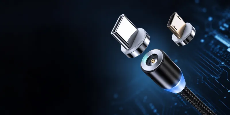
Magnetic USB Connector Guide: Pogo Pins, Retention and USB Signal Integrity
Magnetic USB connectors combine alignment magnets with electrical contacts. They can make docking easier and allow a cable to break away under a pull force, but the magnetic feature does not automatically guarantee USB speed, power capability, sealing or durability. Those properties must be engineered and verified as a system.
Quick comparison
| Design | Typical electrical path | Best fit | Main design risk |
|---|---|---|---|
| Magnetic breakaway adapter | USB-C receptacle plus an adapter interface | Consumer devices, service accessories, light-duty docks | Extra contact interface, exposed contacts and uncertain high-speed performance |
| Integrated pogo-pin connector | Spring contacts on one PCB and mating pads on another | Industrial docks, medical equipment, kiosks and handheld terminals | Alignment, contact wipe, compression travel and PCB tolerance |
| Magnetic wireless alignment | Inductive power; data uses another interface | Wireless charging and alignment aids | Not a wired USB data connection; thermal and efficiency limits |
Important: “Magnetic” describes the mechanical coupling. It does not specify USB 2.0, USB 3.x, USB4, USB Power Delivery or an IP rating.
Magnetic adapter or integrated connector?
Magnetic breakaway adapter
An adapter normally leaves a small insert in the device port and uses magnets to connect the cable end. It can reduce repeated insertion into the host port and may separate when the cable is pulled. The trade-off is an additional interface in the signal and power path.
Before using one in a product, check:
- whether the interface carries USB 2.0 only or SuperSpeed pairs;
- whether the complete path has passed eye-diagram, insertion-loss and interoperability testing;
- whether exposed contacts can short against metal objects;
- whether the adapter remains within the required current and temperature limits;
- whether the breakaway force is safe for the device and enclosure.
Integrated pogo-pin connector
An integrated design places spring-loaded pins on one side and plated pads on the mating side. Magnets help guide the connection, while the pin geometry supplies the normal contact force.
For each pin, define the following in the drawing or specification:
| Parameter | What to specify |
|---|---|
| Working travel | Minimum compression and end-of-travel limit |
| Normal force | Force at the working position, not only free height |
| Contact resistance | Initial value and maximum after environmental/cycle testing |
| Plating | Contact material, underplate, thickness and wear requirement |
| Mating life | Number of cycles, load condition and pass/fail limits |
| Alignment | Magnet polarity, guide features, lateral tolerance and misalignment limit |
Avoid treating a generic “100,000-cycle” statement as a universal rating. Pogo-pin life depends on stroke, wiping action, contamination, current, mating angle and the mating-pad finish.
Pin and signal planning
A simple USB 2.0 connection may require VBUS, D−, D+ and GND, plus shield or detection contacts. A high-speed design needs the appropriate SuperSpeed differential pairs, controlled impedance, short stubs and a carefully designed transition through the magnetic interface.
Use this design sequence:
- Define the required USB speed and whether the product needs USB PD, DisplayPort Alt Mode or only charging.
- Select the minimum pin set that supports those functions.
- Assign power pins separately from high-speed pairs and provide an intentional shield/ground strategy.
- Simulate and test the complete cable-plus-connector channel, not only the connector in isolation.
- Validate hot-plug, polarity, fault current, ESD and repeated docking.
For USB-C adapters, do not infer capability from the 24-pin appearance alone. The cable, adapter interface, receptacle, controller and host must all support the target function.
Magnetic retention force: design it around failure mode
Retention is not a single “stronger is better” number. Measure the force in the directions that matter to the product:
| Application | Design question |
|---|---|
| Desktop dock | Will normal cable movement disconnect the device, or only release the cable? |
| Vehicle or mobile equipment | Can vibration and shock cause intermittent contact? |
| Handheld product | Should a drop release the cable before the enclosure is damaged? |
| Public kiosk | Is a deliberate release needed, or is a lock required? |
Record normal pull-off force, shear force, torque, vibration response and the force after wear. If a breakaway function is required, test it with the actual cable, enclosure and mounting structure.
Verification checklist
- USB protocol and speed test with the final host, cable and device.
- Contact resistance before and after cycling, vibration, humidity and salt contamination where applicable.
- Current rise and temperature at the maximum intended load.
- ESD and surge/fault testing for exposed or user-accessible contacts.
- Misalignment and partial-mating tests to check for intermittent contact or arcing.
- Retention-force distribution across production samples.
- Mechanical life test using the actual mating stroke and operating angle.
How to prepare an RFQ
Give the connector supplier the target USB speed, current/voltage, pin assignment, mating direction, board thickness, keep-out area, magnet position, retention-force range, mating cycles, IP requirement, operating temperature and applicable test standards. A drawing or 3D model of the mating enclosure substantially improves the first proposal.
GSConn can evaluate magnetic and pogo-pin USB concepts according to the required pin configuration, mounting method and environmental conditions. Ask for the specific part drawing, contact plating, electrical limits and validation report for the proposed part before making a production commitment.
FAQ
Can a magnetic USB connector support USB 3.x or USB4?
It can be engineered to do so, but the magnetic interface adds a discontinuity and another mating surface. The complete channel must pass the relevant high-speed signal and interoperability tests.
Is a pogo-pin connector automatically waterproof?
No. Sealing depends on the housing, gasket, cap, drainage path, mating interface and assembly. The IP rating applies only to the tested configuration.
Is a high mating-cycle number enough for a medical or industrial design?
No. Request the test stroke, speed, load, environment, contact-resistance limit and failure criteria behind the rating.
Related reading
Sources
Related reading on GSConn
GSConn application notes that complement this guide: