
Locking Dual USB Connector: Screw-Lock and Latch Options for Stacked USB
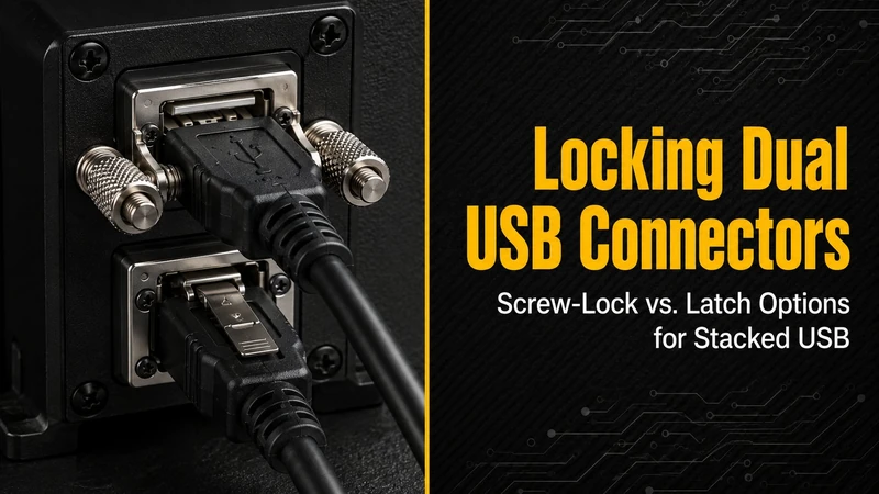
A standard USB cable is designed to be easy to remove. That is convenient on a desk, but it can be a problem in an industrial PC, a mobile medical cart, an outdoor gateway, or a railway cabinet. When unplugging the cable would stop logging, service access, or a safety-related function, the connector needs more than ordinary friction retention.
For stacked USB connectors, the locking choice must also consider port spacing, screw clearance, cable access, and how the pull force is transferred into the product.
Locking options at a glance
| Application | Recommended retention | Why |
|---|---|---|
| Industrial PC / factory HMI | Screw-lock cable + through-hole connector | Good retention and familiar service procedure. |
| Transportation gateway | Screw-lock + chassis support | Vibration and cable pull should not load the PCB pads. |
| Outdoor cabinet | Screw-lock + sealed panel mount | Retention and ingress protection are both needed. |
| Medical cart | Latch or screw-lock, depending on workflow | Locking must be secure but still easy to clean and release. |
| Server management port | Standard retention or light latch | Usually low vibration; service speed matters. |
| Consumer product | Standard friction retention | Locking adds cost and cable constraints. |
1. Why standard USB retention is not enough
USB-A and USB-C connectors rely primarily on spring force and shell geometry. The cable should stay in place during normal use, but the interface is not meant to behave like a circular industrial connector. Repeated vibration, side loading, or a cable routed with tension can produce intermittent contact long before the cable fully falls out.
In the field, the failure often looks random: a log drive disappears, a modem reconnects, a service console drops for a second, or a firmware update fails halfway through. A locking mechanism reduces those failure modes by removing micro-motion and preventing accidental pullout.
2. Screw-lock USB
Screw-lock USB is the most common choice for harsh environments. A small screw in the cable overmold engages with a threaded insert, panel bracket, or connector feature. The screw provides the retention; the USB shell no longer carries the full pull load.
| Design item | Practical guidance |
|---|---|
| Screw size | M2 or M2.5 is common; confirm the cable and receptacle use the same standard. |
| Screw access | Leave clearance for fingers or a small driver, especially on the upper port. |
| Mounting | Through-hole or panel-mount is strongly preferred. Avoid SMT-only screw-lock designs. |
| Serviceability | Use captive screws where possible; loose screws get lost in cabinets. |
| Torque | Use the connector/cable datasheet. Over-tightening can strip plastic or inserts. |
For a stacked connector, each port needs independent access. The top cable may block the bottom screw if the cutout is too tight, so verify the cable overmold in the enclosure model, not just the connector drawing.
3. Latch and pawl-style retention
Latch-style USB is useful where technicians connect and remove cables frequently. It is faster than screws and can be released without tools. The drawback is ecosystem compatibility: the latch feature only works when the cable and receptacle are designed as a pair.
Use latch retention when:
- the device is serviced often;
- a tool-free release is required;
- the cable set is controlled by the equipment manufacturer;
- moderate retention is enough.
Do not specify a latch receptacle and then allow users to buy arbitrary cables. The retention feature may not engage, or the release tab may be inaccessible after installation.
4. Panel-mount locking for high pull force
If cable pull is a real risk, the best mechanical solution is to mount the USB interface to the enclosure panel. The PCB then connects by short cable, flex, or a board-to-board arrangement. This puts the load into the metal or plastic enclosure instead of the solder joints.
Panel-mount locking is preferred for:
- outdoor gateways exposed to service cables;
- railway and vehicle electronics;
- production equipment with moving cable harnesses;
- washdown or dusty environments requiring a sealed panel.
For sealed products, remember that “locking” and “waterproof” are separate requirements. A locking cable may still leave an unsealed interface unless the connector, mating cable, gasket, and panel cutout are designed together.
5. Mounting style matters more than the lock name
A strong cable lock attached to a weak PCB footprint can make the product less reliable. The pull force has to go somewhere.
| Connector mounting | Use with locking? | Comment |
|---|---|---|
| SMT pads only | Avoid | Pads can peel or crack under cable load. |
| SMT + locating posts | Limited use | Acceptable for light retention and controlled access. |
| Through-hole pins + shell stakes | Good | A practical default for industrial stacked USB. |
| Panel mount | Best for high stress | The enclosure carries cable pull and vibration. |
A simple rule: if the product needs a screw-lock cable, it normally also needs through-hole mechanical retention or a panel-mount structure.
6. Medical and cleanable equipment
Medical products add two details that are easy to overlook. First, the release action must be deliberate but not awkward; staff may need to disconnect a cable quickly while wearing gloves. Second, the connector area must be cleanable. Deep screw pockets, exposed threads, and sharp recesses can trap residue.
For medical equipment, ask for material and cleaning compatibility data rather than relying on the phrase “medical grade.” Alcohol wipes, peroxide cleaners, and hospital disinfectants can age plastics and labels. Also confirm whether the USB interface is operator-accessible only or close to patient-applied circuits; isolation and creepage/clearance are device-level design issues.
7. Validation before release
A locking USB design should be validated as a mated assembly. The minimum release package should include the connector, mating cable, panel cutout, gasket or bracket, and the actual enclosure wall thickness. Test cable pull in the directions that can happen in the field: straight pull, side load, upward pull on the upper port, and cable movement while the system is operating.
For screw-lock versions, repeat the test after several connect/disconnect cycles and after any thermal or vibration exposure. A stripped insert, loose screw, or cracked panel boss is a product failure even if the USB link still enumerates on the bench. For latch versions, confirm that the latch can still be released with gloves and that the release tab is not blocked by the neighboring port or enclosure recess.
8. Common design mistakes
Treating the screw as the only mechanical design. The screw retains the cable, but the connector still needs support. Use a bracket or through-hole shell tabs.
Forgetting cable overmold geometry. A cable that fits the connector on the bench may not fit inside a recessed panel.
Mixing incompatible lock systems. Screw pitch, latch shape, and release direction vary. Validate the exact cable part number.
Leaving no service clearance. A locking system that cannot be released in the field will be bypassed by technicians.
Overstating retention force. Retention force is a property of the mated cable assembly, not just the PCB connector. Use tested data for the selected pair.
GSConn selection notes
For GSConn stacked USB projects, specify the application first: vibration, washdown, panel thickness, temperature range, cable direction, and service frequency. Then select the connector family and cable assembly together. Typical requests include stacked USB-A with screw-lock, industrial-temperature through-hole versions, sealed panel-mount versions, and latch-style Type-C options where cable compatibility is controlled.
Before release, confirm the datasheet drawing, mating cable, torque recommendation, panel cutout, and retention test report for the exact part number.