
IoT Gateway Dual USB Connector: Interface Requirements and Layout
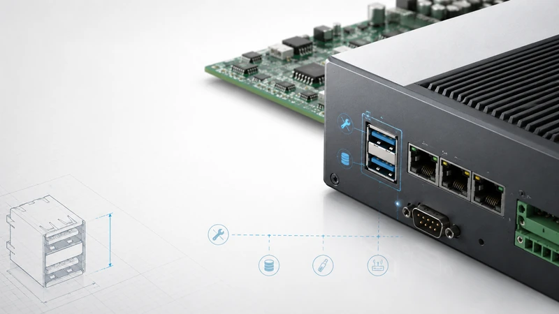
Two USB ports on an IoT gateway are usually not “extra I/O.” In most field products, each port has a job: one is reserved for service access, one is used for storage, a modem, commissioning, or firmware recovery. A stacked USB connector is a good way to keep those two functions available without widening the enclosure or crowding the front panel.
The main design question is not simply “stacked or not.” It is whether the gateway can support two independent USB roles electrically, thermally, mechanically, and in software.
Fast selection guide
| Gateway type | Typical USB use | Better connector choice | Design note |
|---|---|---|---|
| DIN-rail industrial gateway | Console + flash drive | Stacked USB 2.0 Type-A | Add ESD and strain relief; USB 2.0 is normally enough. |
| Edge gateway with camera/storage | SSD + service port | Shielded stacked USB 3.x + USB 2.0 service | Keep SuperSpeed routing short and controlled. |
| Outdoor cabinet | Service port + data logger | Panel-mount stacked USB with seal | The enclosure seal matters as much as the connector rating. |
| Transportation/rail | Debug + maintenance media | Through-hole stacked USB with locking cable option | Avoid SMT-only mechanical retention. |
| Smart-building controller | Commissioning + expansion | Standard stacked USB 2.0/3.x | Consider disabling the service port in production firmware. |
1. Why gateways often need two ports
A gateway is installed once but serviced many times. That is why the first USB port is often a maintenance interface: field technicians use it for a USB-to-UART adapter, a recovery image, log extraction, or a local keyboard. The second port is usually operational: storage, wireless expansion, modem connection, or a temporary commissioning dongle.
A stacked connector is useful when both ports must be accessible from the same panel. Compared with two side-by-side connectors, it reduces panel width and leaves room for Ethernet, antenna feedthroughs, power, SIM access, or status LEDs. The tradeoff is height: a stacked connector needs more vertical clearance and puts more mechanical leverage on the PCB when the upper port is used.
2. Port role planning
Before choosing the connector, assign the two ports. This prevents late changes to the board and avoids confusing service procedures later.
| Port role | Suitable USB speed | Power expectation | Practical notes |
|---|---|---|---|
| Console / recovery | USB 2.0 or Full Speed | Low | Label it clearly. Keep it available even when the application firmware is damaged. |
| Flash drive / log export | USB 2.0 or USB 3.x | 200–900 mA typical | Add a high-side power switch and current limit. |
| External SSD | USB 3.x preferred | 900 mA or higher, depending on drive | Check inrush current, not only steady-state current. |
| LTE/5G modem | Usually internal USB to M.2 or mini PCIe | Bursty current | For external modems, do not assume a Type-A port can safely supply every modem. |
| Wireless dongle | USB 2.0 normally sufficient | 200–500 mA typical | Keep the antenna away from noisy USB 3.x lanes. |
For a robust gateway, avoid tying both ports to the same uncontrolled 5 V rail. Use a current-limited load switch per port so a shorted USB accessory does not pull down the whole gateway.
3. Power budget: where many gateway designs fail
A dual connector does not create power capacity. It only exposes two ports. The 5 V rail must be sized for the worst realistic accessory combination.
A conservative starting point is:
- USB 2.0 service port: budget 500 mA unless intentionally limited lower.
- USB 3.x storage port: budget 900 mA minimum, more if the product supports bus-powered SSDs.
- Modem or high-power accessory: use the accessory datasheet and validate cold-start/inrush current.
For 12 V or 24 V industrial gateways, a dedicated 5 V DC/DC converter for USB is usually cleaner than relying on the SoC or carrier-board regulator. Add per-port power switches with fault reporting to the processor. In field diagnostics, being able to log “USB overcurrent on upper port” is more useful than a generic reboot.
4. Signal and PCB layout notes
For USB 2.0, stacked connectors are generally forgiving. Still route D+/D− as a controlled pair, avoid stubs, and place ESD protection close to the connector.
For USB 3.x, treat the connector as part of the channel, not as a passive mechanical detail.
| Item | Good practice |
|---|---|
| Differential impedance | Target 90 Ω differential for USB 2.0 and SuperSpeed pairs. |
| Layer changes | Keep via count low; if vias are necessary, use a nearby ground via return path. |
| ESD device | Use a low-capacitance TVS array close to the connector pins. |
| Shield grounding | Bond connector shell to chassis or a low-impedance shield ground path. |
| Pair length | Match within each differential pair; do not over-focus on matching unrelated ports. |
| Keep-out | Avoid switching regulators, inductors, and antennas close to the connector opening. |
If the SoC exposes only one USB host controller but the product needs two external ports, the design may need a USB hub controller. Put that decision into the schematic early. A connector change cannot fix a missing host interface.
5. Mechanical and enclosure considerations
IoT gateways live in boxes that are mounted, opened, dropped, and serviced. The connector should be selected with the enclosure, not after it.
Use a through-hole or hybrid through-hole connector when the USB ports are field-accessible. The upper port of a stacked connector creates a larger bending moment during cable insertion, so relying on SMT pads alone is risky for industrial equipment. For high-vibration environments, add a metal bracket or select a panel-mount version so cable loads go into the enclosure instead of the PCB.
For outdoor gateways, the panel seal is the weak point. An IP-rated connector body does not automatically make the finished product IP-rated. The gasket, panel flatness, screw torque, cable gland, and mating cable all need to be validated as an assembly.
6. Software details that improve field service
The hardware can be correct and still annoy technicians if the software does not make the ports predictable.
In Linux-based gateways, document the physical-to-logical mapping:
Upper USB port  -> service / recovery / console accessory
Lower USB port  -> storage / expansion
Use stable device rules where possible. For example, map known USB-to-UART devices by serial number, label the storage port in service documentation, and avoid enabling aggressive autosuspend on devices that are used for logging. If a port may be disabled for cybersecurity reasons, state whether it is disabled only in application software or also at the hub/power-switch level.
7. GSConn selection notes
For GSConn sourcing, the usual gateway starting points are:
- Stacked USB 2.0 Type-A for service + flash drive.
- Shielded stacked USB 3.x when external storage or high-speed peripherals are required.
- Through-hole or panel-mount versions for vibration-prone cabinets.
- Industrial-temperature and sealed variants when the product is used outdoors.
- Locking cable options when accidental unplugging would interrupt service or logging.
Confirm the final part number against the datasheet for current rating, operating temperature, plating, mating cycle rating, mounting style, and panel cutout.
Design review checklist
- [ ] Are the two USB roles defined and labeled on the enclosure?
- [ ] Does the SoC or hub architecture support both ports at the same time?
- [ ] Is each VBUS line current-limited and protected against inrush?
- [ ] Is ESD protection placed at the connector, not several centimeters away?
- [ ] Is the connector mechanically supported for upper-port insertion force?
- [ ] Is the port mapping documented in firmware and service manuals?
- [ ] For outdoor products, has the full panel assembly been sealed and tested?