
Data Center Server Connectors: Complete Guide to I/O Ports, USB, RJ45, and Management Interfaces
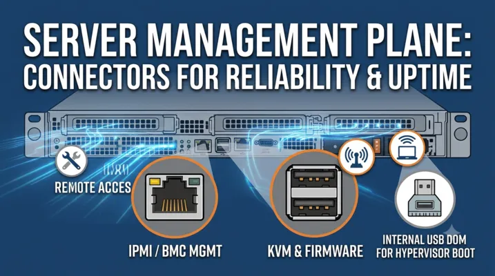
If you build servers, design rack-level infrastructure, or specify components for data center deployment, the I/O connectors on the server panel are not an afterthought. They determine how the server’s management plane operates, how firmware updates are deployed, how console access works when the OS won’t boot, and how many cables the technician needs to carry.
A data center server has two I/O domains: the data plane (the 40G/100G/400G high-speed fabric that carries production traffic — handled by QSFP-DD, OSFP, SFP-DD transceivers and their associated cage connectors) and the management plane (USB ports for BMC/KVM console, RJ45 for IPMI management LAN, serial console headers, and internal USB for hypervisor boot). This guide covers the management plane — the domain where USB, RJ45, and combo connectors determine reliability, serviceability, and uptime.
The Two I/O Domains of a Data Center Server
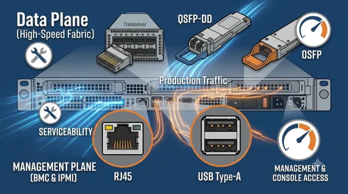
| I/O Domain | Purpose | Typical Connectors | Owner |
|---|---|---|---|
| Data Plane | Production network traffic, storage fabric, inter-node communication | QSFP-DD, OSFP, SFP-DD, SFP+ cages; DAC/AOC cables | Network team / fabric architect |
| Management Plane | BMC/IPMI, KVM console, firmware updates, serial console, boot media | USB Type-A, USB Type-C, RJ45 (1GbE), DB9/serial header, internal USB | Systems team / platform engineer |
The data plane connectors are standardized by the SFF committee and supplied by a handful of vendors (Amphenol, Molex, TE, Samtec). The management plane connectors are more commoditized — and this is where connector quality directly impacts mean time to repair (MTTR), technician experience, and long-term reliability.
A JBOD server sitting in a colocation rack in Frankfurt with a dead OS is completely unreachable unless the BMC management port works. That management port terminates at an RJ45 connector on the rear I/O panel. The quality of that connector — its contact plating, its shield grounding, its mating cycle rating — determines whether the remote administrator can reach the server or has to dispatch a smart hands technician at $150/hour.
USB Connectors on Data Center Servers
Where USB Ports Appear on a Server
A data center server typically has USB ports in three locations:
| Location | USB Type | Quantity | Purpose |
|---|---|---|---|
| Rear I/O panel | USB 2.0 or USB 3.0 Type-A | 2–4 ports | BMC KVM console keyboard/mouse, USB storage for firmware flashing, USB-to-serial adapter for console access |
| Front panel / service panel | USB 2.0 Type-A | 1–2 ports | Technician access for OS installation, diagnostics USB boot, configuration import/export |
| Internal motherboard header | USB 2.0 / USB 3.0 header (9-pin / 19-pin) | 1–2 headers | Internal USB DOM (Disk-on-Module) for hypervisor boot (ESXi, Proxmox), internal storage for OS recovery |
USB 2.0 vs USB 3.0 on Servers
The rear I/O panel on a server is almost universally USB 2.0 for the management port — and this is deliberate, not a cost-cutting measure:
- BMC chips (ASPEED AST2500/2600, Pilot 4/5, Nuvoton) typically have a USB 2.0 host controller built into the BMC SoC. Adding a USB 3.0 host controller requires a separate USB 3.0 PHY chip, additional power, and additional board routing — all for a port that moves keyboard/mouse HID reports at 12 Mbps and occasionally transfers a firmware image.
- USB 2.0 has longer cable reach in electrically noisy environments. A USB 2.0 signal at 480 Mbps tolerates 5 meters of cable with adequate margin. USB 3.0 at 5 Gbps degrades beyond 3 meters in the same rack environment due to cable crosstalk from adjacent Ethernet bundles.
- USB 2.0 connectors have higher mating cycle ratings in standard designs. A USB 2.0 Type-A receptacle is rated for 1,500–5,000 mating cycles with a simple 4-pin contact. A USB 3.0 Type-A adds 5 additional SuperSpeed pins that are thinner and more susceptible to wear — typical rating is 1,500–3,500 cycles.
USB Type-C on Servers: Not Yet, But Coming
Server adoption of USB Type-C on the I/O panel has been slow, but the reasons are changing:
| Historically Blocked | Why | Status 2026 |
|---|---|---|
| BMC lacks USB-C controller | Most BMC SoCs have USB 2.0 root hubs; Type-C requires USB 3.x host controller for full feature set | ASPEED AST2700 supports USB 3.2; future BMCs will have native Type-C capability |
| Reversible connector irrelevant for servers | Servers aren’t plugged/unplugged by feel — the connector is directly visible; reversibility adds cost without value | Still true — but Type-C is becoming the de facto standard regardless |
| PD power from a server port is unwanted | A server outputting 100W on a USB port creates thermal and power budget issues; nobody wants a server as a phone charger | USB PD can be disabled in BIOS/design — Type-C can operate as a data-only port |
| Legacy compatibility | A KVM crash cart expects USB Type-A keyboard/mouse; Type-C requires adapters | Adapters are now commodity — and KVM-over-IP has largely replaced crash carts |
The transition to Type-C on servers will happen as BMC SoCs add native Type-C support, but it will be driven by standardization pressure, not server-specific requirements. For now and the next 3–5 years, USB Type-A remains the dominant server management connector.
RJ45 Management Ports: The Server’s Lifeline
What Is the Management RJ45 Port?
Every server with a BMC has a dedicated RJ45 port labeled “Mgmt,” “IPMI,” “BMC,” or with a wrench icon. This port is electrically separate from the primary data network ports. It connects to a dedicated management NIC inside the BMC chip, not to the server’s OS-visible network controller.
The management port uses standard Gigabit Ethernet (1000BASE-T) over Cat5e/Cat6 cable with an RJ45 connector — but the connector and its magnetics module are more critical here than on a consumer device, because:
- The management port must work when the server is powered off. The BMC is powered from the standby rail (+5VSB) whenever AC power is present. If the RJ45 connector has poor contact or the magnetics module has degraded, the server is unreachable — and there’s no OS-level fallback because the OS isn’t running.
- The management port may carry PoE in non-standard applications (some edge deployments use PoE-powered BMCs). The connector must handle the additional current without contact heating or arc damage during disconnection.
- The management port is the single point of contact for the server’s health. CPU temperature, fan speed, power supply status, DIMM errors, PCIe errors — all of this telemetry flows through one RJ45 connector.
Integrated Magnetics vs. Discrete Magnetics
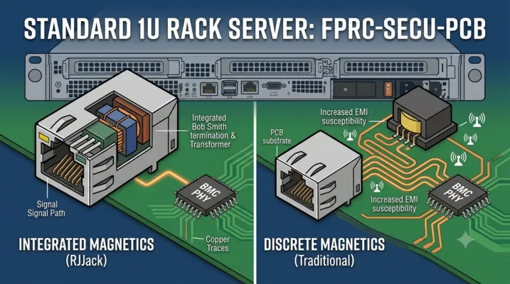
The Ethernet magnetics module (isolation transformer, common-mode choke, termination resistors, Bob Smith termination, and sometimes the PHY-side center tap) can be integrated into the RJ45 connector housing or placed as discrete components on the PCB:
| Parameter | Integrated Magnetics RJ45 | Discrete Magnetics |
|---|---|---|
| Board space | One component footprint | RJ45 jack + magnetics chip + routing area |
| EMI/EMC | Pre-tested as a system; internal shielding between magnetics and connector | Layout-dependent; transformer-to-jack trace length adds EMI susceptibility |
| Common-mode rejection | Optimized by connector manufacturer | Dependent on PCB layout quality |
| Cost | Higher per connector (~$2.50 vs $0.80 + discrete parts) | Lower BOM cost but higher layout and compliance cost |
| Reliability | Single vendor-tested module; fewer solder joints | Multiple components; more failure points |
| Typical application | Server BMC ports, industrial switches | High-volume consumer routers |
For data center servers, integrated magnetic RJ45 jacks are standard. The $0.80 savings from discrete magnetics disappear when a single server outage caused by a marginal Ethernet connection costs more than 10,000 jacks.
RJ45 Contact Plating and Mating Cycles
The RJ45 jack’s contact pins and the plug’s gold-plated contacts are the actual electrical interface. In a data center, a server management port might see:
| Scenario | Plugs/Unplugs Over 5-Year Life |
|---|---|
| Rack-and-forget deployment | 2–5 (initial cable + occasional re-patch) |
| Colocation facility with frequent customer changes | 15–30 |
| Test lab / burn-in rack | 50–100+ |
| Server used as a deployment staging unit | 200+ |
A standard RJ45 jack is rated for 750 mating cycles. A high-durability variant with 50µ” gold plating over nickel on the contacts can achieve 2,000+ cycles. For a data center server, even the standard 750-cycle rating is adequate — but the contact normal force (how hard the plug pins press against the jack pins) and the plating durability determine long-term reliability when the connector sits undisturbed for years in a vibration-prone rack environment.
The correct specification is:
- Contact plating: Minimum 30µ” gold over 50µ” nickel on phosphor bronze contacts
- Contact normal force: 100g minimum per contact (8 contacts, 8P8C)
- Housing material: UL 94V-0 rated PBT or PA66 with glass fiber reinforcement
- Shielding: Full 360° metal shell with grounding tabs to chassis
Combo and Stacked Connectors for Server Front Panels
The Space Problem on 1U and 2U Servers
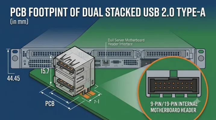
A 1U server is 1.75 inches (44.45 mm) tall. The front panel needs to accommodate:
- Power button + LED
- System ID button + LED
- 1–2 USB ports
- Optional: VGA or serial console port
- Optional: drive activity LEDs
- Optional: LCD diagnostic panel
All of this must fit within a vertical space smaller than a credit card. The USB connectors alone are 15.7 mm tall with their PCB footprint. Adding two USB connectors, a power button, an ID button, and LEDs in that space requires careful layout — or stacked connector solutions.
Stacked USB Connectors in Server Panels
A stacked USB connector places two USB receptacles in a single housing, one above the other. This cuts the horizontal PCB space requirement in half:
| Configuration | Horizontal PCB Width (Single Connector) | Occupied with Stacked |
|---|---|---|
| 2× USB Type-A (side by side) | ~30 mm | ~17 mm (stacked) |
| 2× USB Type-A + RJ45 | ~47 mm | ~32 mm (combo stacked) |
| USB Type-A + USB Type-C | ~30 mm | ~17 mm (stacked) |
For a 1U server front panel, the width saved by using stacked connectors is often the difference between a workable layout and a board respin.
RJ45 + USB Combo Jacks for Management
The combination of an RJ45 port and a USB port in a single stacked housing — covered in detail in our RJ45 USB combo jack guide — is directly applicable to server front panels where the management console port and the technician access USB port need to coexist in minimal space. The Ethernet port on top provides the management LAN connection; the USB port below provides local console or firmware update access.
Connector Specifications That Matter for Data Center Deployment
Operating Temperature
Data center hot aisles can reach 35–40°C. A connector’s housing material must not soften or deform at these temperatures:
| Housing Material | Continuous Operating Temperature | UL 94 Rating |
|---|---|---|
| Standard PBT | 105°C | V-0 |
| Glass-reinforced PA66 | 125°C | V-0 |
| LCP (Liquid Crystal Polymer) | 220°C | V-0 |
| PASF (Polyarylamide) | 150°C | V-0 |
For server rear I/O panels, which are exposed to the hot aisle exhaust airflow (typically 30–45°C, with localized hotspots near CPU and GPU exhaust up to 55°C), PA66 or PBT at minimum is required. LCP is over-spec for the I/O panel but is used for internal board-to-board connectors near the CPU socket.
Mating Cycles and Service Life
A data center server has a 3–5 year operational life, with more frequent service interactions during deployment and decommissioning:
| Server Role | USB Port Cycles (5 years) | RJ45 Port Cycles (5 years) |
|---|---|---|
| Hyperscale (fixed config, no local maintenance) | 5–10 | 2–5 |
| Enterprise (quarterly maintenance, occasional reconfig) | 20–50 | 10–20 |
| Colocation / multi-tenant | 50–100 | 20–50 |
| Lab / staging / test | 100–300 | 50–100 |
For the USB ports, a 1,500-cycle minimum rating covers all but lab/staging scenarios. For RJ45, 750 cycles is sufficient for all deployment types.
EMI Shielding and Grounding
Servers in a data center rack sit inches apart. The adjacent server’s CPUs, memory, and power supplies generate electromagnetic interference across a broad spectrum — from 100 MHz (baseband switching noise) to 10+ GHz (memory bus harmonics). An unshielded or poorly grounded USB connector acts as an antenna, coupling this noise into the USB differential pair and causing:
- Intermittent USB device enumeration failures during high-CPU-load periods on adjacent servers
- USB storage write errors when the server above it runs a memory stress test
- Keyboard/mouse lag on the KVM console coincident with GPU compute workloads on neighboring blades
The mitigation is straightforward:
- Full 360° metal shell shielding on the USB receptacle, with grounding tabs that make contact with the chassis
- The chassis grounding path must have impedance below 10 mΩ from the connector shell to the rack ground
- For stacked connectors, internal metal dividers between the USB and RJ45 cavities prevent Ethernet magnetics noise from coupling into USB signals
Contact Resistance and Current Rating
USB 2.0 VBUS carries 5 V at up to 500 mA (2.5 W). USB 3.0 raises this to 900 mA (4.5 W). At these currents, contact resistance becomes measurable:
| Contact Resistance | Voltage Drop at 500 mA | Power Lost at Connector |
|---|---|---|
| 30 mΩ (standard) | 15 mV | 7.5 mW |
| 50 mΩ (after wear) | 25 mV | 12.5 mW |
| 100 mΩ (damaged/contaminated) | 50 mV | 25 mW |
At 25 mW, the connector isn’t physically hot — but the 50 mV drop can push a USB device powered by a marginal 4.75 V supply below the 4.40 V USB minimum, causing brownout resets. For server USB ports, the specification should require:
- Initial contact resistance: ≤ 30 mΩ per contact
- After durability test (1,500 cycles): ≤ 50 mΩ
- Current rating: 1.5 A per VBUS pin (target 1.0 A continuous, the USB 3.0 maximum, with 50% margin)
Connector Types by Server Form Factor
| Server Form Factor | Front Panel Connectors | Rear I/O Panel Connectors | Internal Headers |
|---|---|---|---|
| 1U Rack Server | 1–2× USB 2.0 Type-A, power button, ID button, status LEDs | 2–4× USB 2.0/3.0 Type-A, 1× RJ45 Mgmt, 1× DB9 serial (optional), 1× VGA (optional) | 1× USB 2.0 header (9-pin), 1× USB 3.0 header (19-pin) |
| 2U Rack Server | 2× USB 2.0/3.0 Type-A, power button, ID, LEDs, optional VGA or LCD | 4× USB 2.0/3.0 Type-A, 1× RJ45 Mgmt, 1× serial, 1× VGA | 1–2× USB 2.0 header, 1× USB 3.0 header |
| 4U Rack / Tower | 2–4× USB Type-A (mix 2.0/3.0), 1× USB Type-C (newer models), audio jacks, SD card | 4–6× USB Type-A, 2× RJ45 (Mgmt + shared), 1× serial | 2× USB 2.0, 1× USB 3.0, 1× Type-C header (newer boards) |
| Blade Server | Minimal — 1× USB (service), 1× power button | Blade midplane connector (proprietary high-density) | Limited — blade chassis provides I/O |
| Edge Server / Micro DC | 1–2× USB, 1× RJ45 combo jack | 2× USB, 1× RJ45 Mgmt, 1× optional rugged USB | 1× USB header |
Edge Data Center Considerations
Edge data centers — deployed in retail back rooms, factory floors, cell tower bases, and outdoor cabinets — impose additional connector requirements:
| Requirement | Standard DC Server | Edge Server |
|---|---|---|
| Temperature range | 10–35°C operational | −5 to 55°C operational (extended range) |
| Humidity | 20–80% RH non-condensing | 5–95% RH condensing possible |
| Dust / particulates | Filtered air (MERV 8–13) | Unfiltered or minimal filtration |
| Vibration | Low (concrete floor, isolated rack) | Moderate to high (factory floor, transportation) |
| Connector protection | Standard | IP65+ panel sealing, locking USB, shrouded RJ45 |
| Mating cycle expectation | 50–100 over 5 years | 100–500 over 5 years (more frequent technician access) |
For edge deployments, industrial-grade USB connectors — with locking mechanisms, IP65/IP67 sealing, and extended temperature-range housings — replace standard server connectors. A locking USB connector with a screw-lock or bayonet mechanism prevents accidental disconnection when the enclosure is accessed by non-IT personnel in a non-controlled environment. A waterproof RJ45 with IP67-rated sealing prevents condensation and dust ingress in outdoor cabinets.
RJ45 Connector Specifications by Ethernet Speed
The management port runs at 1 Gbps, but servers also have data network ports at higher speeds. The connector requirements change at each speed tier:
| Ethernet Speed | Connector Type | Cable | Max Distance | Connector-Specific Notes |
|---|---|---|---|---|
| 10/100 Mbps | RJ45, 8P8C, Cat5 | Cat5/5e UTP | 100 m | Standard magnetics; minimal crosstalk concern |
| 1000 Mbps (1GbE) | RJ45, 8P8C, Cat5e+ | Cat5e/6 UTP | 100 m | Requires 100 MHz bandwidth magnetics; echo cancellation depends on impedance match between jack and PCB |
| 2.5 Gbps (2.5GBASE-T) | RJ45, 8P8C, Cat5e+ | Cat5e/6 | 100 m | More sensitive to return loss; integrated magnetics RJ45 preferred |
| 5 Gbps (5GBASE-T) | RJ45, 8P8C, Cat6 | Cat6/6A | 100 m | Requires Cat6-rated magnetics; PCB layout around RJ45 is critical |
| 10 Gbps (10GBASE-T) | RJ45, 8P8C, Cat6A | Cat6A/7 | 100 m / 30 m (Cat6) | 500 MHz bandwidth requirement; alien crosstalk between adjacent jacks is the limiting factor |
| 25/40 Gbps | SFP28/QSFP+ cage | DAC/AOC/fiber | 5 m (DAC) / 100 m+ (fiber) | Not RJ45; transitions to SFP/QSFP connector cage form factor |
For server design, the management port connector and the 10GbE data port connector appear identical — both are RJ45 jacks — but the 10GbE jack has significantly tighter specifications on return loss and crosstalk. Specifying a 1GbE-grade RJ45 jack on a 10GbE data port will cause link training failures and fallback to 1GbE.
BMC-Specific USB Connector Requirements
The BMC is the server’s embedded management controller. It has specific USB connector requirements that differ from a standard USB hub port:
BMC USB Port as a Host
The BMC acts as a USB host to devices plugged into the server’s management USB ports. This means the BMC USB controller must:
- Provide VBUS power (5 V, 500 mA minimum) continuously when standby power is present — even when the server is in S5 (soft-off) state. This requires the USB VBUS power rail to be sourced from +5VSB, not from the main +5V rail.
- Handle USB device hot-plugging during BMC boot. The BMC may enumerate a USB device while the server OS is booting, and the device must remain enumerated when the OS takes over the non-management USB ports.
- Support USB device classes that the BMC needs: HID (keyboard/mouse for KVM), MSC (mass storage for virtual media firmware updates), and CDC (communications device class for USB-to-serial adapters).
Virtual Media: Why USB 3.0 on the Management Port Matters
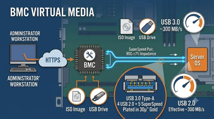
Virtual Media allows a remote administrator to mount an ISO image or USB drive from their local machine to the server as if it were physically plugged in. The BMC presents this as a virtual USB mass storage device. The data path is:
Administrator's workstation → HTTPS → BMC → USB MSC device class → Server OS sees a USB drive
With USB 2.0, the virtual media transfer rate is limited to approximately 30 MB/s (effective, with protocol overhead). With USB 3.0, this increases to approximately 300 MB/s. For a 5 GB OS installation ISO, that’s the difference between a 2.8-minute mount time and a 17-second mount time.
This is the strongest argument for USB 3.0 management ports on servers — not for keyboard/mouse, but for virtual media performance. Servers with USB 3.0 management ports should use USB 3.0-grade connectors with:
- All 9 contacts (4 USB 2.0 + 5 SuperSpeed) plated to 30µ” gold minimum
- Differential impedance of 90Ω ±7% on the SuperSpeed pair
- Shielded differential pair routing from connector to BMC USB 3.0 PHY
Connector Reliability: What Actually Fails in a Data Center
Connector failures in data center servers follow a predictable pattern:
| Failure Mode | Root Cause | Frequency | Prevention |
|---|---|---|---|
| USB port physically damaged (bent contacts, cracked housing) | Technician plugs cable at an angle; cable yanked sideways while inserted | Most common USB failure | Through-hole USB connectors (vs SMT) with reinforcing mounting pegs; metal shell with flange |
| RJ45 jack clip retainer cracked | Plug inserted/removed with clip not fully depressed; repeated high-force extraction | Common RJ45 failure | High-grade PBT housing with glass fiber reinforcement; integrated LED light pipes that don’t weaken the housing structure |
| USB port intermittent connection | Contact oxidation (sulfur-rich data center air); contact normal force relaxation over years | Gradual onset, harder to diagnose | 50µ” gold plating over nickel; sealed connector option for high-sulfur environments; dual-beam contact design |
| RJ45 magnetics degradation | Environmental: high humidity causes moisture absorption in the magnetics potting; temperature cycling cracks the ferrite | Rare but catastrophic | Epoxy-encapsulated magnetics module; conformal coating on exposed PCB area |
| USB port completely dead (no VBUS) | ESD damage to BMC USB PHY through the connector; surge from a damaged USB device | Infrequent but immediate | ESD protection diodes on VBUS, D+, D− lines; TVS array rated for IEC 61000-4-2 Level 4 (8 kV contact, 15 kV air) |
Selection Checklist for Server USB and RJ45 Connectors
| Requirement | USB Connector Specification | RJ45 Connector Specification |
|---|---|---|
| Interface standard | USB 2.0 (BMC ports) / USB 3.0 or 3.2 Gen 1 (front panel and rear data ports) | 1000BASE-T (management) / 10GBASE-T (data) |
| Mounting type | Right-angle, through-hole preferred (SMT acceptable if reinforced with through-hole pegs) | Right-angle, through-hole with panel grounding tabs |
| Contact plating | 30µ” gold min over nickel on phosphor bronze contacts | 50µ” gold over nickel on phosphor bronze contacts |
| Housing material | UL 94V-0 PBT or PA66-GF | UL 94V-0 PBT or PA66-GF |
| Shell | Full metal shell, 360° shielding, chassis grounding tabs | Full metal shell with integrated EMI spring fingers |
| Mating cycles | 1,500 (standard) / 5,000 (high-durability) | 750 (standard) / 2,000 (high-durability) |
| Operating temperature | −20 to +85°C (standard) / −40 to +105°C (extended-range for edge) | −40 to +85°C |
| Current rating | 1.5 A per VBUS pin (with margin) | Per IEEE 802.3 PoE class requirements if PoE-supported |
| Integrated magnetics | N/A | 1000BASE-T magnetics module integrated into jack, with CM choke and Bob Smith termination |
| Flammability | UL 94V-0 | UL 94V-0 |
| ESD protection | External TVS array on VBUS, D+, D− (not in connector, but specified here for design reference) | External TVS on center tap, external ESD diodes on MDI pairs |
| Compliance | USB-IF certified (USB 2.0 or 3.2) | IEEE 802.3ab (1GbE) / IEEE 802.3an (10GbE); FCC Part 15 Class A, EN 55032 |
Internal USB Headers: Hypervisor Boot and Security Dongles
USB DOM (Disk-on-Module)
Hypervisors like VMware ESXi, Proxmox VE, and XenServer are often booted from an internal USB DOM — a small USB flash drive that plugs directly into an internal USB header on the motherboard. This frees the drive bays for storage and keeps the hypervisor boot drive physically inside the chassis.
The internal USB header is a 9-pin (USB 2.0) or 19-pin (USB 3.0) IDC-style header. The connector on the DOM side is typically a shrouded 10-pin female header. Key considerations:
- Retention force: The DOM must not work loose from vibration. Some server motherboards use a locking USB header with side clips. If using a standard friction-fit header, a dab of hot glue or a retention bracket is common in production.
- Vertical vs. horizontal header orientation: A vertical header accepts a DOM that stands straight up — this limits component height above the board. A right-angle header allows the DOM to lie flat — better for 1U enclosures but requires PCB edge mounting.
- Power: USB 2.0 DOMs consume 200–500 mA at 5 V. This is drawn from the standby rail, so the DOM is powered whenever AC power is present. A failed DOM that shorts VBUS can bring down the standby rail and prevent the server from powering on.
Internal USB for Security Modules
Some server platforms use an internal USB port for a hardware security module (HSM) or a platform root of trust dongle. This USB port is often a dedicated internal header that is not wired to the front or rear I/O panel, so the security module cannot be accessed from outside the chassis.
GSConn supplies USB Type-A, USB Type-C, RJ45, and RJ45+USB combo jack connectors for server I/O panels, with options for integrated magnetics, stacked configurations, and industrial-grade variants for edge data center deployment. Contact our engineering team for connector specifications, samples, and volume pricing.
GSConn supplies USB Type-A, USB Type-C, RJ45, and RJ45+USB combo jack connectors engineered for data center server I/O panels. Our server-grade portfolio includes integrated-magnetics RJ45 jacks rated for 1GbE management ports, vertical-mount and right-angle USB 2.0/3.0 Type-A receptacles, USB Type-C receptacles with full 24-pin support, and stacked/combo configurations that reduce front-panel footprint by up to 40%. Industrial-temperature variants (-40 to +105 °C) and IP67-sealed options are available for edge and outdoor data center deployments. Custom pinout, plating thickness (15–50 µ”), and PCB footprint support are provided for OEM server designs.
Related Reading: Stacked USB connector design guide · RJ45 + USB combo jack reference · Waterproof IP67/IP68 stacked USB connectors · USB connector manufacturer selection guide · Industrial USB connector design and selection