
Locking USB Connectors: Complete Guide to Retention Mechanisms and Applications
Standard USB connectors rely on friction to stay seated. The plug slides in, the housing geometry and contact spring force create enough resistance to stay in place — most of the time. In a laptop bag or a living room, that’s adequate. In a medical infusion pump, an industrial robot, or a server in a vibrating equipment rack, it isn’t.
A locking USB connector adds a positive retention mechanism that resists extraction forces exceeding the friction threshold. The connector cannot be accidentally disconnected without intentional release. This guide covers the locking mechanisms available across USB generations, the applications that require them, and how to select the right locking type for a given use case.
Why Standard USB Connectors Disconnect Accidentally
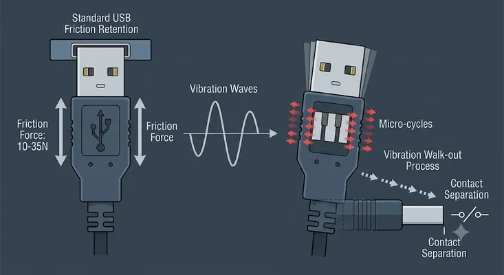
The USB specification defines a minimum insertion/extraction force — but not a maximum retention force under vibration or sustained loading. The USB 2.0 Type-A receptacle is specified at:
- Insertion force: ≤ 35N
- Extraction force: 10–35N
- Vibration resistance: Not specified in the base USB-IF standard
In static environments, 10–35N extraction force is adequate. Under vibration, the dynamic loading cycles the contact spring back and forth, gradually reducing effective clamping force. The connector walks out of the receptacle over thousands of micro-cycles — a process that takes seconds to seconds in high-vibration environments even when no one is near the cable.
The consequences depend on the application:
| Application | Consequence of Accidental Disconnection |
|---|---|
| Server USB management port | Disconnects active KVM console session; lost during active remediation |
| Medical device USB logging | Incomplete procedure data; potential regulatory non-compliance |
| Industrial robot USB programming | Machine stops mid-program; potential safety incident |
| Vehicle infotainment USB | Navigation data loss, audio interruption |
| Scientific instrument USB | Lost experimental run; data corruption |
| Outdoor sensor USB | Undetected disconnect; weeks of missing data |
Locking USB Connector Mechanisms
Screw-Lock (Threaded Coupling)
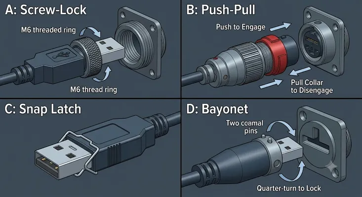
The most common industrial locking mechanism. A threaded ring or barrel on the plug mates with a threaded receiver on the receptacle. The coupling screws clockwise to engage and counterclockwise to release.
Configuration:
– Outer ring on plug body contains fine thread (typically M6, M8, or UNC 4-40)
– Receptacle has matching internal thread (or external thread with lock nut)
– Engagement length: 3–8 mm of thread contact
Retention force: > 45N (vs. 10–35N friction-only)
Typical applications: Industrial automation, data center equipment, outdoor terminals
Trade-offs:
– Requires 2–4 turns to engage/disengage — slow for frequent connections
– Thread can cross-thread if rotational alignment is off at insertion
– Thread wear over many cycles (typically > 5,000 cycles before degradation)
USB versions available: USB 2.0 Type-A, USB 3.0 Type-A, USB Type-C (M-series lock ring)
Push-Pull (Click Latch)
A spring-loaded latch engages a shoulder on the receptacle body when the plug is fully seated. Release requires pushing a button or collar rearward before extracting.
Configuration:
– Latch arm(s) on plug housing engage rectangular slot or undercut on receptacle body
– Push-to-release: single button on plug body; no rotation required
– Color indicator: some designs include visual indicator (red visible = not fully seated)
Retention force: 20–45N (varies by design)
Typical applications: Test and measurement, medical equipment, industrial HMI, military handhelds
Trade-offs:
– Faster than screw-lock (single press and pull)
– Lower retention force than screw-lock
– Proprietary interface — push-pull plug requires matching push-pull receptacle (not compatible with standard receptacles)
– Slightly larger plug diameter
USB versions available: USB 2.0 Type-A, USB 3.0 Type-A, USB Type-C (recent versions)
Snap Latch (Spring Clip)
A metal or plastic spring clip on the receptacle body engages a notch or shoulder on the plug. The clip is engaged/disengaged by pressing a release lever.
Configuration:
– Retention clip is on the receptacle (unlike push-pull which is on the plug)
– Older military connector heritage (MIL-DTL-38999 style retention concept adapted for USB)
– Compatible with standard USB plugs — no special plug required
Retention force: 15–30N
Typical applications: Automotive, military, applications where cable replacement is needed without replacing the plug
Trade-offs:
– Field cable replacement is easier — any standard USB plug works
– Lower retention force than screw-lock
– Clip can fatigue and lose spring tension over many cycles
Bayonet Coupling
Quarter-turn engagement: insert, rotate 90°, locked. Reverse rotation to release.
Configuration:
– L-shaped bayonet slots on receptacle body engage pins on plug collar
– Full engagement achieved in < 1/4 turn — faster than screw-lock
– Common in military and aerospace connector traditions (adapted for USB from BNC/MIL-C style)
Retention force: > 50N (excellent)
Typical applications: Military, aerospace, medical imaging equipment, high-cycle industrial
Trade-offs:
– Higher cost and larger outer diameter than screw-lock
– Requires bayonet receptacle — not backward-compatible with standard plugs
– Less common in USB form factor; primarily available for industrial USB 2.0 Type-A
Magnetic Retention (Not a Locking Mechanism)
Magnetic USB connectors (seen in some consumer accessories) use magnetic alignment and retention. These are explicitly not suitable for industrial locking applications:
- Retention force is typically 2–8N — easily defeated by vibration or cable tension
- Magnetic field can affect nearby sensors, memory media, or sensitive electronics
- Not available in industrial/server grade configurations
Magnetic USB is for consumer convenience (e.g., preventing cable trip damage). It is not a locking mechanism.
USB Type Compatibility Matrix
| Locking Type | USB 2.0 A | USB 3.0 A | USB Type-C | Backward Compatible? |
|---|---|---|---|---|
| Screw-lock | ✅ Common | ✅ Available | ✅ M-ring variants | Plug: No (ring adds diameter). Receptacle: Yes (screw ring optional on plug) |
| Push-pull | ✅ Common | ✅ Available | ✅ Available | No — requires matching receptacle |
| Snap latch | ✅ Available | ✅ Available | Limited | Partial — depends on latch design |
| Bayonet | ✅ Available | Limited | Limited | No — requires bayonet receptacle |
Critical note on Type-C locking: USB Type-C’s 24-contact shell requires more careful retention design than Type-A’s 4+5 contact layout. The Type-C screw-lock mechanism adds a collar around the 8.94mm plug body without engaging the contacts — retention is purely mechanical, relying on the collar thread to prevent extraction. Force applied at an angle during locked extraction must be transferred to the panel, not to the contacts, to avoid damage.
Application Deep Dives
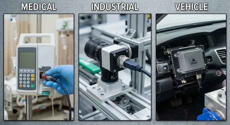
Medical Device Applications
Medical devices with USB connectivity face specific regulatory requirements. The IEC 60601-1 standard for medical electrical equipment, and its collateral standards (particularly IEC 60601-1-2 for EMC and IEC 60601-1-6 for usability), influence connector selection indirectly:
- Cable retention: USB cables connected to medical devices should not create trip hazards or patient entanglement risk — locking connectors that require intentional release prevent accidental pulls from becoming incidents
- Disinfection compatibility: Hospital-grade cleaning agents (quaternary ammonium compounds, hydrogen peroxide wipes) degrade standard USB connector housings. Connectors in medical environments need housings rated for these chemicals.
- EMI shielding: Locking screw-coupling connectors typically have better shell-to-shield continuity than friction connectors — the threaded engagement maintains shell contact throughout the mating duration
For patient-attached equipment (Type BF and CF applied parts per IEC 60601-1), the USB connector may need to be on the isolated side of the circuit. The connector choice affects the isolation barrier design.
Recommended locking type for medical: Push-pull — fast enough for frequent cable changes in clinical workflows, no rotation confusion for gloved users, adequate retention force.
Industrial Automation
In industrial automation, USB appears at several points in the system hierarchy:
| USB Interface | Typical Application | Vibration Level |
|---|---|---|
| PLC programming port | Laptop-to-PLC for program upload/download | Low (periodic access) |
| HMI USB | Memory stick for recipe/parameter import | Low-medium |
| Robot controller USB | Laptop-to-robot for programming | Low (workshop) |
| Machine vision USB | Camera-to-controller data interface | Medium-high |
| Motor drive USB | Parameter backup port | Low-medium |
| Encoder feedback USB | Machine axis data (rare; CAN/EtherCat usually preferred) | High |
For machine vision cameras — where a USB 3.0 connection carries 2–5 Gbps of raw image data continuously — a screw-lock USB 3.0 Type-A connector is standard practice. The alternative is a Vision System USB retention clip specific to Basler/FLIR/Allied Vision cameras.
Industrial vibration reference: IEC 60068-2-6 defines vibration test conditions. Category 3 (0–500 Hz, up to 10g) is typical for industrial equipment mounted near machinery. At 10g vibration, a 50g USB plug exerts peak dynamic loads of 0.5N — small compared to a 15N friction force, but with resonance effects and long exposure, connector walk-out is documented in deployed equipment.
Automotive and Transportation
In vehicles, USB connectors appear in:
- Center console charge/sync ports (consumer — friction lock adequate)
- Instrument cluster and head unit data interfaces (behind the dash — locking required)
- ADAS camera and sensor USB data interfaces (vibration-critical)
- Diagnostic OBD-USB adapters (removable — friction adequate)
- Fleet management USB dongles (permanent installation — locking preferred)
Vehicle vibration per ISO 16750-3 includes 10–2,000 Hz sweeps, multi-axis simultaneous vibration, and mechanical shock up to 25g. For behind-panel USB connections, screw-lock Type-A or bayonet USB connectors with operating temperature ratings to −40°C/+85°C are standard.
Automotive USB connectors must also meet:
| Requirement | Typical Specification |
|---|---|
| Operating temperature | −40°C to +85°C (HALT tested to +105°C) |
| Humidity | 5–95% RH, condensing |
| Salt spray | 96 hours per ISO 9227 |
| Contact resistance stability | < 30 mΩ after 1,000 hours exposure |
| Vibration | 25g peak, all axes, per ISO 16750-3 |
Data Center and Server
Server USB locking applications:
| Location | Locking Mechanism | Justification |
|---|---|---|
| BMC rear panel USB | Screw-lock Type-A | Low mating cycles; high retention required for uptime |
| KVM cable retention | Screw-lock or retention clip | Prevents cable weight from disconnecting during active session |
| Internal DOM header | Clip retention on DOM device | Vibration from chassis fans |
| Front panel service USB | Friction (standard) | Intentionally removable; locking inappropriate |
See the Server BMC USB Connector guide for full data center USB specification.
Locking USB Connector Standards
There is no single USB-IF standard for locking mechanisms. Several industry standards address locking connectors in the USB form factor:
| Standard | Coverage | Relevance |
|---|---|---|
| IEC 61076-3-106 | Push-pull circular connectors including USB implementations | Defines test methods for retention force, mating cycles, IP rating with locking |
| MIL-DTL-38999 (applied concepts) | Military circular connector retention — adapted in industrial USB variants | Military and aerospace applications |
| USB-IF EMC testing | Does not address retention — EMC compliance separate from locking | Background standard only |
| SEMI E78 | Semiconductor equipment USB interfaces (informative only) | Fab and wafer equipment |
In practice, connector manufacturers (Amphenol, TE Connectivity, Souriau, GSConn) specify locking connectors to their own test standards, referencing IEC 60068 for environmental testing and specifying retention force directly in the datasheet.
Selecting the Right Locking Type
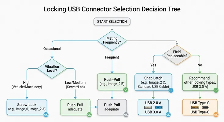
Use this decision framework when specifying a locking USB connector:
Mating frequency?
├── Occasional (monthly or less)     → Screw-lock (maximum retention)
├── Regular (weekly)                 → Screw-lock or push-pull
└── Frequent (daily or more)         → Push-pull (fastest release)

Vibration environment?
├── High (vehicle, machinery)        → Screw-lock or bayonet
└── Low/medium (server, lab)         → Push-pull adequate

Cable field-replaceable?
├── Yes (use standard USB cable)     → Snap latch receptacle, or screw-lock with standard plug option
└── No (dedicated cable assembly)    → Push-pull or screw-lock with custom plug

IP rating required?
├── IP67/IP68                        → Screw-lock with O-ring; or push-pull with IP-rated housing
└── IP20                             → Any mechanism

USB generation?
├── USB 2.0 Type-A                   → All mechanisms available
├── USB 3.0 Type-A                   → Screw-lock or push-pull; verify SuperSpeed contact retention
└── USB Type-C                       → Screw-lock M-ring or push-pull; fewer options than Type-A
Key Specifications to Request from Suppliers
When requesting datasheets or samples for locking USB connectors:
Retention force (axial): Minimum force required to extract the mated connector. Should exceed the expected cable tension and vibration-induced load by 3× safety margin.
Locking engagement torque/force: For screw-lock, the torque required for full engagement. Over-torqueing can damage the thread; under-torqueing leaves the lock partially engaged.
Rated mating cycles with locking mechanism engaged: A connector rated 5,000 cycles must maintain retention force specification after 5,000 complete mate-demate cycles of the locking mechanism, not just the contact spring.
Compatibility with standard plugs: Confirm whether the receptacle engages with standard USB plugs (for screw-lock with ring-on-plug, the receptacle is standard; for push-pull, confirm receptacle-and-plug must match).
IP rating in mated vs. unmated condition: IP rating often applies only when mated. Confirm cap IP rating for unmated condition.
Environmental range: Operating temperature, humidity, salt spray, and vibration per referenced standards.
Summary
Standard USB friction retention fails in applications where vibration, sustained cable tension, or accidental pull can disconnect the interface at a critical moment. Locking USB connectors add a retention mechanism — screw, push-pull, snap latch, or bayonet — that maintains connection integrity under these conditions.
The choice of mechanism depends on three factors: how often the cable needs to be connected and disconnected (frequency drives toward push-pull for convenience); how severe the vibration environment is (severity drives toward screw-lock for retention); and whether field replacement with standard cables is needed (drives toward snap-latch on the receptacle side).
In data center, medical, and industrial applications, the cost difference between a standard USB receptacle and a locking variant is small relative to the cost of a service interruption or data loss event caused by accidental disconnection.
Related guides: Industrial USB Connector Guide | Panel Mount USB Connector Guide | How to Waterproof a USB Connector
GSConn offers screw-lock and push-pull locking USB connectors in Type-A (USB 2.0 and USB 3.0) and Type-C configurations. IP67-rated locking variants available for outdoor and industrial panel mount applications.
GSConn supplies locking USB Type-A, USB Type-C, micro-USB, and Mini-B connectors with screw-lock, bayonet, latch, and threaded-coupling retention mechanisms. Our locking portfolio includes IP67/IP68-sealed variants for harsh-environment deployment, MIL-spec-rated options for defense and aerospace, and stacked USB+RJ45 locking configurations that combine data retention with panel-mount robustness. Industrial-temperature variants (-40 to +105 °C) and custom cable assemblies with locking terminations are available for OEM integration.
Related Reading: USB Connector for Industrial Equipment · Waterproof USB Connector: IP67/IP68 · Industrial USB Connector Selection · Panel Mount USB Connector Guide · Stacked Connector Selection Guide