
USB Type-C Connector: The Complete Guide
USB Type-C Connector: The Complete Guide
Introduction
The USB Type-C connector landed in 2014 with the USB 3.1 specification. Ten years on, it has done what no connector standard before it managed: replace nearly every data and charging port on consumer electronics. Laptops, phones, monitors, power banks, docking stations — the list keeps growing. The EU’s Common Charger Directive (EN IEC 62680) made USB-C mandatory for most portable devices sold after December 2024, cementing its position as the default connector.
But the physical connector is only half the story. The same 24-pin reversible shell can carry USB 2.0 at 480 Mbps or USB4 at 80 Gbps. It can deliver 15W of power or 240W. It can transmit DisplayPort video, Thunderbolt data, or analog audio. This versatility creates confusion — not every USB-C port supports everything, and not every USB-C cable is built for every task.
This guide covers what engineers, system designers, and technically-minded buyers need to know about USB-C connectors: pinout architecture, power delivery, data protocols, cable types, the latest 2024 specification updates, and how to avoid the most common integration mistakes.
1. The Physical Connector: 24 Pins, Symmetrical Design
1.1 Connector Anatomy
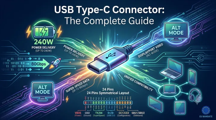
The USB-C connector uses 24 pins arranged in a symmetrical layout. This symmetry is what makes it reversible — the pin mapping on one side mirrors the other, so the connector works in either orientation.
| Pin Group | Count | Pins | Function |
|---|---|---|---|
| VBUS (Power) | 4 | A4, A9, B4, B9 | Bus power, up to 48V / 5A with PD 3.1 |
| GND (Ground) | 4 | A1, A12, B1, B12 | Power return path |
| TX/RX (SuperSpeed) | 8 | A2-A3, A10-A11, B2-B3, B10-B11 | 4 differential pairs for USB 3.x / USB4 / Alt Mode |
| D+/D- (USB 2.0) | 4 | A6-A7, B6-B7 | Legacy USB 2.0 data (internally connected, single channel) |
| CC1 / CC2 | 2 | A5, B5 | Configuration channel — orientation detection, power negotiation |
| SBU1 / SBU2 | 2 | A8, B8 | Sideband use — DisplayPort AUX, analog audio in Audio Adapter Accessory Mode |
The key insight: multiple VBUS and GND pins are wired in parallel to handle high current. At 5A, a single pin contact would overheat. Spreading the load across four power pins and four ground pins keeps contact resistance manageable.
1.2 Receptacle vs. Plug
USB-C receptacles and plugs are not pin-for-pin identical. The receptacle (mounted on the device PCB) contains all 24 contacts. The plug (on the cable end) has only one set of functional contacts per pin position — the CC pin on one side becomes VCONN on the plug side, used to power active cable electronics (E-Marker chips, re-drivers, re-timers).
A full-featured USB-C cable contains 18 internal wires: 4 for VBUS, 4 for GND, 1 pair for D+/D-, 4 pairs for SuperSpeed, 1 for CC, 2 for SBU, and 1 for VCONN. Charge-only cables omit the SuperSpeed and SBU conductors to reduce cost and thickness.
2. Configuration Channel (CC): The Intelligence Layer
The CC pins are what separate USB-C from every previous USB connector. They turn a passive connector into an active negotiation interface.
2.1 Orientation Detection
When a plug is inserted, only one of the two CC pins (CC1 or CC2) makes contact with the receptacle. The port controller detects which pin is connected and routes signals accordingly. This happens in milliseconds, before any data or power negotiation begins.
2.2 Power Role and Current Capability
The CC pins use a simple resistor-divider detection scheme before any digital communication starts:
| Source (DFP) Rp Value | Advertised Current | Typical Use |
|---|---|---|
| 56 kΩ | Default USB power (500 mA / 900 mA) | Standard downstream port |
| 22 kΩ | 1.5 A | USB BC 1.2 compatible |
| 10 kΩ | 3.0 A | USB-C with 5V/3A capability |
The Sink (UFP) applies a 5.1 kΩ pull-down (Rd) to ground. When Source and Sink connect, the voltage divider formed by Rp and Rd tells the Source what the Sink needs — and whether an electronically marked cable is present.
2.3 USB Power Delivery Communication
For anything beyond the basic 5V/3A (15W), the CC line switches to digital communication using Bi-Phase Mark Coding (BMC) at approximately 300 kHz. This is where the USB PD protocol runs: negotiating voltage, current, power role swaps, and Alternate Mode entry.
3. USB Power Delivery: From 15W to 240W
3.1 The Evolution of USB PD
USB Power Delivery has gone through three major revisions:
| PD Version | Max Power | Voltage Range | Key Features |
|---|---|---|---|
| PD 1.0 (2012) | 100W | 5V, 12V, 20V | Fixed PDOs only |
| PD 2.0 / 3.0 | 100W | 5V, 9V, 15V, 20V | PPS (Programmable Power Supply), role swap |
| PD 3.1 (2021) | 240W | Up to 48V | Extended Power Range (EPR), 28V, 36V, 48V PDOs |
3.2 Standard Power Range (SPR) vs. Extended Power Range (EPR)
SPR covers up to 100W (20V @ 5A). This is what most current laptops, monitors, and docking stations use. The fixed PDOs — 5V, 9V, 15V, 20V — plus PPS allow fine-grained voltage steps for direct-charge battery architectures in phones.
EPR, introduced with PD 3.1, pushes the ceiling to 240W (48V @ 5A). This is aimed at gaming laptops, compact desktop PCs, and higher-power peripherals. EPR requires:
- Both port and cable to be EPR-capable
- 5A-rated E-Marker cable (standard 3A cables cannot be used)
- Strict cable voltage drop and insulation testing per USB-IF compliance
3.3 E-Marker Chips
Any cable capable of more than 3A or supporting SuperSpeed data rates above USB 2.0 must contain an E-Marker — a small IC embedded in one or both plugs that reports the cable’s capabilities. The E-Marker communicates over the CC line and stores:
- Maximum current rating (3A or 5A)
- USB data speed rating (Gen 1, Gen 2, Gen 3)
- USB4 and Thunderbolt support flags
- Vendor ID and cable type
Without an E-Marker, the system defaults to 3A / USB 2.0. This is why a cheap USB-C cable may charge a laptop slowly or fail to drive a 4K monitor — it lacks the E-Marker and the internal SuperSpeed wiring.
4. Data Protocols: One Connector, Many Standards
4.1 Speed Tiers
The USB-C physical connector is protocol-agnostic. The same shell and pinout can carry any of these:
| Protocol | Max Speed | Lanes Used | Notes |
|---|---|---|---|
| USB 2.0 | 480 Mbps | D+/D- only | Always available, independent of SuperSpeed |
| USB 3.2 Gen 1 | 5 Gbps | 1 TX + 1 RX | Formerly USB 3.0, then USB 3.1 Gen 1 |
| USB 3.2 Gen 2 | 10 Gbps | 1 TX + 1 RX | Single-lane 10 Gbps |
| USB 3.2 Gen 2×2 | 20 Gbps | 2 TX + 2 RX | Uses all four SuperSpeed pairs |
| USB4 Gen 2×2 | 20 Gbps | 2 TX + 2 RX | USB4 base speed |
| USB4 Gen 3×2 | 40 Gbps | 2 TX + 2 RX | Requires active cable beyond ~0.8m |
| USB4 Gen 4 (v2.0) | 80 Gbps | 2 TX + 2 RX | PAM-3 signaling, asymmetric mode up to 120/40 Gbps |
| Thunderbolt 3 | 40 Gbps | 2 TX + 2 RX | Intel specification, now folded into USB4 |
| Thunderbolt 4 | 40 Gbps | 2 TX + 2 RX | Mandatory USB4 compliance, stricter requirements |
| Thunderbolt 5 | 80/120 Gbps | 2 TX + 2 RX | PAM-3, asymmetric bandwidth |
4.2 USB 2.0 Always Present
One underappreciated design choice: USB 2.0 D+/D- lines are always available regardless of what the SuperSpeed lanes are doing. This means a dock using all four SuperSpeed pairs for dual 4K DisplayPort can still handle keyboard, mouse, and USB audio through the USB 2.0 channel. It also means USB-C to USB-A adapters need only connect VBUS, GND, D+, D-, and CC (with pull-down) — no SuperSpeed wiring required.
4.3 Alternate Mode: USB-C as a Video and Audio Port
Alternate Mode is the mechanism that lets USB-C carry non-USB protocols. The most widely deployed is DisplayPort Alt Mode:
- 2-lane DP: Uses two SuperSpeed pairs for video, leaving two pairs for simultaneous USB 3.x data
- 4-lane DP: Uses all four SuperSpeed pairs for maximum video bandwidth (up to 8K); USB data falls back to 2.0
- SBU pins: Carry the DisplayPort AUX channel for EDID, HDCP, and link training
- DP 2.1 (UHBR20): Up to 80 Gbps raw bandwidth via USB-C Alt Mode, supporting 8K@60Hz uncompressed or 16K with DSC
HDMI Alt Mode exists but saw limited adoption — most implementations use DisplayPort Alt Mode with a DP-to-HDMI converter in the adapter or dock. Thunderbolt Alt Mode effectively subsumes both, carrying PCIe and DisplayPort natively over USB-C.
5. The USB-C Specification R2.4 (October 2024)
USB-IF released the Type-C Cable and Connector Specification Revision 2.4 on October 28, 2024. Four major areas were updated:
5.1 New Product Certification Categories
R2.4 expands the USB-C certification scope to cover additional product types that previously fell outside formal compliance programs. This includes:
– USB-C receptacles integrated into multi-port hubs with shared power architectures
– Charging-only USB-C cables (previously uncertified for PD use)
– USB-C power adapters with multiple output ports
5.2 Improved Test Methodologies
Test procedures were refined to better reflect real-world use cases:
– Updated VBUS voltage drop measurement across cables at full rated current
– Stricter contact resistance limits for receptacles after environmental stress testing
– New insertion/withdrawal force profiles to address wear from frequent connect/disconnect cycles in industrial and automotive applications
5.3 E-Marker and Cable Compliance
R2.4 tightens E-Marker requirements:
– Mandatory E-Marker for any cable claiming USB4 or Thunderbolt support
– Enhanced E-Marker data fields for reporting supported Alternate Modes
– Standardized test vectors for validating E-Marker-to-PD-controller communication
5.4 Alignment with IEC 62680
The specification aligns with IEC 62680-1-3:2024, the international standard that underpins the EU Common Charger Directive. Key alignments include:
– Harmonized mechanical dimensions and tolerances
– Unified PD power rules for charger interoperability
– Consistent labeling requirements for certified products
6. Cable Selection: Not All USB-C Cables Are Equal
6.1 Cable Classification
USB-C cables fall into categories based on their internal construction and E-Marker data:
| Cable Type | Max Current | Max Data Speed | Internal Wires | E-Marker Required |
|---|---|---|---|---|
| Charge-only (3A) | 3A | USB 2.0 (480 Mbps) | ~8-10 | No |
| Charge-only (5A) | 5A | USB 2.0 (480 Mbps) | ~8-10 | Yes |
| USB 3.2 Gen 1 (5 Gbps) | 3A or 5A | 5 Gbps | 15-18 | Yes (if 5A) |
| USB 3.2 Gen 2 (10 Gbps) | 3A or 5A | 10 Gbps | 18 | Yes |
| USB4 / TBT3 (40 Gbps) | 5A | 40 Gbps | 18 | Yes |
| USB4 Gen 4 / TBT5 (80 Gbps) | 5A | 80 Gbps | 18 (active) | Yes |
6.2 Passive vs. Active Cables
Passive cables rely on raw copper conductors. For 40 Gbps (USB4 Gen 3), passive cables are typically limited to 0.8 meters. Longer 40 Gbps cables require active components — re-timers or re-drivers — that clean up the signal, consuming power from VCONN.
USB4 Gen 4 (80 Gbps) cables are essentially all active beyond very short lengths (0.2-0.3m), using PAM-3 modulation which is more sensitive to signal degradation than NRZ.
6.3 Common Cable Pitfalls
- A 100W-labeled cable may only support USB 2.0 data: Many “100W” cables are charge-optimized with no SuperSpeed pairs
- A Thunderbolt 3 cable is not necessarily a Thunderbolt 4 cable: TBT4 mandates USB4 compliance and 40 Gbps on all ports; TBT3 does not
- USB4 Gen 4 cables are backward compatible but speed-limited: Plugging an 80 Gbps cable into a USB4 Gen 3 host works, but only at 40 Gbps
- Cable length matters for data but not for power: A 2m 5A charge-only cable charges fine; a 2m passive 40 Gbps data cable may not work at all
7. PCB Design Considerations
7.1 Connector Footprint and Mechanical
USB-C receptacles come in several mounting styles:
– Top-mount (SMT): Sits on the PCB surface; most common
– Mid-mount (SMT): Centered in PCB thickness; used in thin devices
– Vertical: Stands perpendicular to PCB
– Hybrid (SMT + through-hole): SMT signal pins with through-hole anchor tabs for mechanical strength
The through-hole anchor variant is strongly recommended for applications with frequent cable insertion/removal. Pure SMT connectors can lift pads over time if mechanical strain relief is insufficient.
7.2 High-Speed Signal Routing
SuperSpeed differential pairs (TX1+/-, TX2+/-, RX1+/-, RX2+/-) require controlled impedance routing:
– Target impedance: 85-90 Ω differential
– Length matching: Within 5 mils within each pair; within 100 mils between lanes on the same bus
– Minimize layer transitions: Every via adds a discontinuity
– Ground stitching vias: Alongside differential pairs to maintain return path continuity
USB 2.0 D+/D- pairs also need 90 Ω differential impedance but are more forgiving at 480 Mbps.
7.3 Power Routing
At 5A, even small trace resistances matter:
– A 10 mΩ trace carrying 5A dissipates 0.25W — manageable but noticeable
– Use wide traces or copper pours for VBUS and GND paths
– Place ceramic bypass capacitors (10 µF + 0.1 µF) near the connector VBUS pins
– For EPR designs (48V), creepage and clearance requirements per IEC 62368-1 apply — standard 0.5mm pitch USB-C footprints may need review
7.4 ESD and Protection
USB-C ports face frequent ESD events from cable insertion in uncontrolled environments:
– Low-capacitance TVS diodes (< 0.5 pF) on CC, SBU, and SuperSpeed lines
– VBUS overvoltage protection — a failing charger can dump 20V onto a 5V rail
– VCONN current limiting — prevents short-circuit damage in active cable electronics
8. USB-C in Industrial Applications
While USB-C originated in consumer electronics, industrial adoption is growing rapidly.
8.1 Ruggedized USB-C
Standard USB-C connectors are rated for 10,000 insertion cycles — far better than Micro-B (1,500) but insufficient for harsh environments. Industrial variants add:
- IP67/IP68 sealing: Gasketed receptacles and mating connectors for wet/dusty environments
- Bayonet or screw-lock retention: Prevents accidental disconnection under vibration
- Extended temperature range: -40°C to +85°C or wider
- Reinforced mounting: Metal shell with panel-mount flanges
8.2 Single-Cable Solutions
USB-C’s ability to carry power, data, and video over one cable makes it attractive for industrial HMIs, machine vision cameras, and test equipment. A single USB-C connection can:
– Power a 15W industrial touch panel
– Stream 1080p60 video via DisplayPort Alt Mode
– Transmit USB 2.0 touch and sensor data
– All through one sealed, locking connector
8.3 USB4 for Machine Vision
USB4 Gen 3 (40 Gbps) and the newer Gen 4 (80 Gbps) open possibilities for high-bandwidth machine vision cameras that previously required Camera Link HS or CoaXPress. USB4’s PCIe tunneling (via Thunderbolt compatibility) also enables direct GPU access for real-time image processing.
9. Certification and Compliance
9.1 USB-IF Certification
USB-IF certification is voluntary but increasingly expected by OEMs and system integrators. Certified products appear in the USB-IF Product Search database. Certification covers:
- Electrical compliance (signal integrity, PD protocol)
- Mechanical compliance (dimensions, insertion force, durability)
- Cable compliance (E-Marker accuracy, voltage drop, crosstalk)
- Interoperability testing with reference hosts and devices
9.2 EU Common Charger Directive (IEC 62680)
Since December 28, 2024, the EU Radio Equipment Directive mandates USB-C as the common charging port for:
– Mobile phones and tablets
– Digital cameras
– Headphones and headsets
– Handheld video game consoles
– Portable speakers, e-readers, keyboards, mice, and navigation systems
Laptops have until April 28, 2026, to comply. The directive references IEC 62680-1-3:2024 (USB Type-C) and IEC 62680-1-2:2024 (USB PD), making USB-IF specifications effectively regulatory requirements in the EU market.
10. Looking Ahead: What’s Next for USB-C
10.1 USB4 Version 2.0 (80/120 Gbps)
Announced in 2022, USB4 v2.0 doubles throughput using PAM-3 signaling (three voltage levels per symbol instead of NRZ’s two). It also introduces asymmetric mode: 120 Gbps in one direction, 40 Gbps in the other — optimized for docking and display applications.
10.2 Higher Power Delivery
PD 3.1’s 240W ceiling covers most current devices, but the USB-IF has indicated that further EPR extensions may follow as data center and industrial applications demand more power over a single cable. The limiting factor is not the specification but the physics of connector contact resistance — at 48V/5A, each VBUS pin already carries 1.25A, and further current increases require either more pins or lower contact resistance.
10.3 Automotive USB-C
USB-C is appearing in automotive infotainment, rear-seat entertainment, and ADAS camera interfaces. The automotive grade (AEC-Q100) USB-C ecosystem is still maturing, but the single-cable video+power+data capability is compelling for reducing wiring harness weight and complexity.
10.4 The End of Proprietary Charging
With the EU mandate and similar regulations under consideration in India, Brazil, and other markets, proprietary charging connectors (Apple Lightning, various barrel jacks) are on a clear path to obsolescence. USB-C is becoming the universal connector — not just for data, but for power delivery up to 240W.
FAQ
Q: Can a USB-C port that supports DisplayPort also charge my laptop?
A: Not necessarily. DisplayPort Alt Mode and USB PD are independent capabilities. A monitor’s USB-C port may carry video (DP Alt Mode) without providing power, or provide 15W while not supporting video. Check the port’s listed capabilities, not just the connector shape.
Q: Are all USB-C cables capable of 240W charging?
A: No. Only EPR-rated cables (48V, 5A, with appropriate E-Marker) support 240W. Standard 100W (20V/5A) cables cannot handle 48V safely. Using a non-EPR cable with an EPR charger will limit power to 100W or lower.
Q: How do I know if a USB-C cable supports video?
A: Look for “SuperSpeed” or “USB 3.x” in the specifications. A cable that only mentions “charging” or “USB 2.0” lacks the SuperSpeed pairs needed for DisplayPort Alt Mode. USB-IF certified cables display data rate logos (5 Gbps, 10 Gbps, 20 Gbps, 40 Gbps, 80 Gbps).
Q: What happens if I plug a USB4 device into a USB 3.2 host?
A: USB4 devices are backward compatible. They fall back to the highest speed both sides support — typically USB 3.2 Gen 2 (10 Gbps) or USB 2.0. Thunderbolt-specific features (PCIe tunneling) will not work without a Thunderbolt or USB4 host.
Q: Is USB-C the same as Thunderbolt?
A: No. Thunderbolt 3 and 4 use the USB-C connector but require specific host controller hardware (Intel or certified third-party). USB4 incorporates Thunderbolt 3 compatibility, but not all USB4 ports support PCIe tunneling. Thunderbolt certification guarantees specific minimum performance levels that USB4 does not mandate.
References: USB-IF Type-C Cable and Connector Specification R2.4 (October 2024), USB Power Delivery Specification R3.2, USB4 Specification v2.0, IEC 62680-1-3:2024, TI Engineer’s Guide to USB Type-C.