
RJ45 USB Combo Jack: Integrated Stacked Connector for IoT & Industrial Gateways
RJ45 USB Combo Jack: Integrated Stacked Connector for IoT & Industrial Gateways
If you design IoT gateways, industrial routers, or networked embedded systems, you’ve probably faced this panel layout problem: you need one Ethernet port and one USB port, they need to sit next to each other on the same face of the enclosure, and you’re running out of PCB edge space.
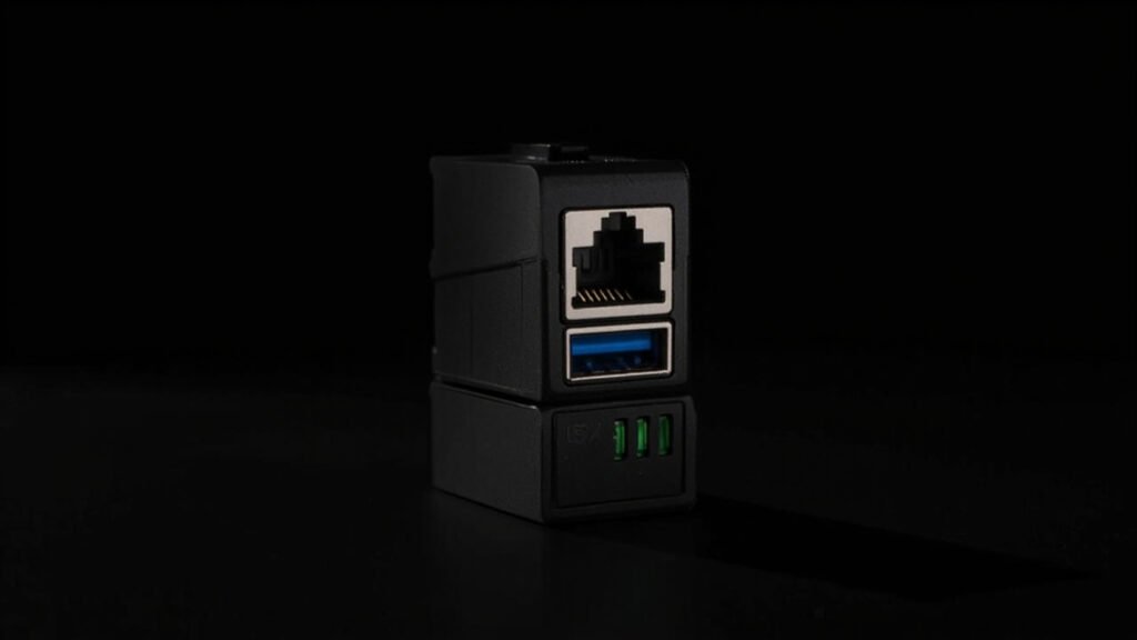
An RJ45 USB combo jack solves this by combining an RJ45 Ethernet connector and a USB Type-A receptacle into a single stacked housing — Ethernet on top, USB on the bottom (or vice versa, depending on the variant). One component, one cutout, one placement. Your panel layout gets simpler, your BOM gets shorter, and your assembly line has one less part to align.
What Exactly Is an RJ45 USB Combo Jack?
It’s a stacked connector that integrates two different interface standards in one housing:
| Feature | Typical Configuration |
|---|---|
| Upper port | RJ45, 8P8C, with or without integrated magnetics |
| Lower port | USB Type-A (2.0 or 3.0) |
| RJ45 features | Shielded, with LED indicators (link/activity) |
| USB version | USB 2.0 (480 Mbps) or USB 3.0 (5 Gbps) |
| Mounting | Right-angle DIP or SMT + panel grounding tabs |
| Optional | PoE-capable RJ45, locking USB variant, IP-rated sealing |
The combination of Ethernet + USB in one connector is particularly powerful for industrial and IoT applications because these two interfaces serve complementary roles: Ethernet for always-on network connectivity, USB for local configuration, firmware updates, and peripheral attachment.
Why Not Separate Connectors?
Using separate RJ45 and USB connectors means:
- Two PCB cutouts that must be precisely aligned relative to each other
- Two separate placements on the pick-and-place line
- Two separate panel openings in the enclosure (twice the tolerance stackup)
- More PCB edge space consumed (typically 30–35mm vs 18–20mm for a combo jack)
- Two separate EMI grounding paths to manage
A combo jack collapses all of that into one part. The panel opening is a single rectangular cutout. The placement is a single operation. The EMI grounding path is unified.
The BOM savings are modest — maybe $0.50–1.00 per unit — but the real benefit is assembly simplicity and reduced tolerance stackup. When you’re building 10,000 industrial gateways, eliminating one alignment step on the line is worth more than the BOM delta.
RJ45 USB Combo Jack Variants
Standard RJ45 + USB 2.0
The most common variant. RJ45 on top with integrated magnetics and dual LED indicators (green for link, yellow for activity). USB 2.0 Type-A on the bottom. Right-angle DIP mounting.
Typical applications: Industrial IoT gateways, edge computing nodes, building automation controllers, network-attached sensors.
Key specs:
- RJ45: 10/100/1000Base-T, integrated magnetics, 1.5 kV isolation
- USB: USB 2.0, 480 Mbps, 4 contacts
- Temperature: 0–70°C (commercial) or −40 to +85°C (industrial)
RJ45 + USB 3.0
Same form factor but the USB port is SuperSpeed (5 Gbps) with 9 contacts instead of 4. The connector body is slightly taller to accommodate the extra SuperSpeed contact row.
Key difference from USB 2.0 variant: Signal integrity requirements. The USB 3.0 SuperSpeed traces run alongside the RJ45 magnetics inside the combo housing, creating potential for electromagnetic coupling between the Ethernet transformer and the 5 Gbps USB data lines.
A well-designed RJ45 USB 3.0 combo jack includes an internal shield plate between the RJ45 magnetics cavity and the USB 3.0 contact area. Without this, you’re likely to see Ethernet noise coupling into the USB SuperSpeed lanes — especially when PoE is present on the RJ45 port, where the DC current through the magnetics creates a stronger magnetic field in the adjacent USB contact zone.
RJ45 PoE + USB 2.0
The RJ45 port supports Power over Ethernet (802.3af/at, up to 30W). The combo jack must handle the additional thermal load from the PoE current going through the integrated magnetics, and the internal shielding needs to isolate the PoE DC path from the USB data lines.
Thermal note: PoE magnetics dissipate about 0.5–1.0W of heat (depending on current). In a sealed industrial enclosure, this can raise the internal temperature by 5–10°C. Make sure your combo jack’s housing material is rated for the operating temperature plus this thermal rise — LCP or PPS housings are recommended, not standard PBT.
Signal Integrity in Combo Connectors
The fundamental challenge in any RJ45 USB combo jack is electromagnetic compatibility between two very different signal types sharing one housing:
| Signal Type | Frequency Range | Sensitivity |
|---|---|---|
| Ethernet (1000Base-T) | 62.5 MHz per pair (PAM5, 125 MBd) | Moderate — differential, transformer-coupled |
| USB 2.0 | 240 MHz (480 Mbps) | Moderate — differential, but single-ended VBUS and D+/D− |
| USB 3.0 SuperSpeed | 2.5 GHz (5 Gbps) | High — differential, wideband |
At USB 3.0 speeds, the Ethernet magnetics switching at 125 MHz can create harmonics in the 2.5 GHz range. A combo jack without adequate internal shielding will show elevated noise floor on the USB 3.0 receiver, manifesting as occasional bit errors under heavy Ethernet traffic.
What to verify with your supplier:
- Is there an internal metal shield between the RJ45 magnetics cavity and the USB contact area?
- Is the shield connected to chassis ground or signal ground?
- For USB 3.0 combo jacks, is there eye diagram or compliance test data with Ethernet traffic active?
Industrial-Grade Requirements
For industrial applications (factory floor, outdoor cabinet, transportation), the combo jack needs to survive conditions that would destroy a consumer-grade connector:
Temperature
Industrial: −40 to +85°C operating. This requires LCP or PPS housing material with a glass transition temperature (Tg) above 260°C, and magnetics rated for the full temperature range. Standard RJ45 magnetics with ferrite cores can shift inductance by 10–15% at −40°C, which affects Ethernet signal integrity.
Vibration & Shock
RJ45 connectors with integrated magnetics have more mass than a simple pass-through jack. In a vibration environment (e.g., railway equipment, heavy machinery), the mass of the magnetics module inside the combo jack housing can create mechanical stress on the solder joints. Through-hole DIP mounting with additional board-lock tabs or screw-down flanges is recommended over SMT for vibration-prone applications.
Sealing
Panel-sealed combo jacks with an elastomeric gasket around the connector face can achieve IP65 or IP67 ratings. The gasket compresses against the enclosure panel when the PCB is mounted, sealing both the RJ45 and USB openings simultaneously. One gasket, one sealing surface — simpler than sealing two separate connectors.
Comparing RJ45 USB Combo Jacks to Alternatives
| Solution | RJ45 USB Combo Jack | Separate RJ45 + USB | USB-to-Ethernet Adapter (external) |
|---|---|---|---|
| Panel openings | 1 | 2 | 1 (USB only) |
| PCB space | ~18–20mm panel width | ~30–35mm panel width | Single USB connector |
| BOM line items | 1 | 2 | 1 (+ external adapter) |
| Assembly steps | 1 placement | 2 placements + alignment | 1 placement + external accessory |
| Serviceability | Replace entire unit | Replace bad port only | Replace adapter separately |
| EMI management | Single grounding path | Two grounding paths | External adapter, uncontrolled |
| Cost (1k qty) | $1.50–4.00 | $1.00–2.50 (combined) | $0.50 + adapter cost |
The external adapter approach is tempting for low-cost designs, but it means the customer carries an accessory that can get lost or damaged. For industrial equipment that’s installed once and expected to work for 10+ years, a built-in combo jack is the right call.
Application Examples
Industrial Edge Gateway
An edge gateway in a factory collects sensor data over Ethernet and provides a local USB port for technician laptops to pull diagnostic logs. The combo jack puts both interfaces on a single face of the DIN-rail enclosure, simplifying panel machining and assembly.
Recommended: RJ45 1000Base-T with magnetics + USB 2.0, industrial temperature range, panel seal optional.
EV Charging Station Communication Module
The communication module inside an EV charger uses Ethernet for OCPP protocol back to the charging network operator and USB for local firmware updates and configuration. Both ports need to be accessible from the outside of the sealed electronics enclosure.
Recommended: RJ45 PoE-capable (if the module is PoE-powered) + USB 2.0, IP65 panel seal, −40 to +85°C, vibration-rated.
Building Automation Controller
A BACnet/IP controller serves as a building automation hub. Ethernet for the building network, USB for commissioning tools and backup. Installed in a mechanical room with temperature swings and humidity.
Recommended: RJ45 10/100Base-T with magnetics + USB 2.0, IP54 minimum panel seal, extended temperature range.
Network Security Appliance
A firewall or VPN appliance with multiple Ethernet ports. One combo jack provides an out-of-band management Ethernet port plus a USB console port in one panel position, freeing up panel space for additional data ports.
Recommended: RJ45 1000Base-T with magnetics + USB 2.0 (console only, no USB 3.0 needed).
What to Look for When Sourcing
LED Configuration
Most RJ45 combo jacks include two LEDs (link and activity) integrated into the RJ45 housing. Verify the LED color, forward voltage, and current limiting resistor requirements match your design. Common configurations: green/yellow or green/orange, 2.0–2.2V forward voltage, 10–20mA drive current.
Magnetics Specification
Integrated magnetics in the RJ45 section should meet IEEE 802.3 requirements:
- Insertion loss: <1.0 dB at 100 MHz
- Return loss: >16 dB at 100 MHz
- Common-mode rejection: >30 dB at 100 MHz
- Isolation voltage: 1.5 kVrms minimum
USB Contact Life
The USB port in a combo jack sees the same usage patterns as a standalone USB connector. Make sure the contact life rating (minimum 1,500 cycles for standard, 5,000+ for industrial) applies to the combo jack as a whole — some suppliers rate the RJ45 separately from the USB, and you need both numbers.
Summary
RJ45 USB combo jacks are one of those components that seem simple until you look closely at the engineering. In a well-designed combo jack, Ethernet magnetics and USB SuperSpeed signals coexist peacefully behind adequate internal shielding. In a poorly designed one, they interfere in ways that are expensive to debug.
For industrial and IoT designs, specify:
- LCP or PPS housing for temperature range and reflow compatibility
- Internal shield between magnetics and USB (mandatory for USB 3.0)
- Verified LED polarity and forward voltage
- Panel sealing option if your enclosure requires IP rating
- DIP mounting with board locks for vibration environments
GSConn’s RJ45 USB combo jack portfolio covers USB 2.0 and USB 3.0 variants with integrated magnetics, LED indicators, industrial temperature options, and IP67 sealed panel-mount designs.