
“Wire-to-Board vs Board-to-Board Connectors: How to Choose in 2026”

Wire-to-Board vs Board-to-Board Connectors: How to Choose in 2026
Meta Description: Wire-to-Board or Board-to-Board? A practical decision guide for engineers — when each makes sense, how to compare them, and what to spec in your next RFQ.
Reading time: ~8 minutes
Best for: Hardware engineers, EE designers, and procurement leads choosing connector topology for a new PCB design.
Introduction
“Should this be wire-to-board or board-to-board?”
It’s the question that comes up in every hardware review, and the answer is almost never “it depends” — but figuring out which of the two it should be usually takes an hour of whiteboarding, a stack of catalog PDFs, and at least one meeting that overruns.
Both topologies solve the same problem (electrically joining two circuits) but they do it in fundamentally different ways, and the wrong pick cascades into mechanical redesigns, harness changes, and field-service complications.
This guide gives you a clear decision framework. In about 8 minutes, you’ll know:
- The mechanical and electrical difference between WTB and BTB
- A side-by-side comparison table for spec sheets
- A 4-question decision flowchart you can use in your next design review
- Common mistakes that force a redesign at DV/PV stage
- Which GSCONN categories to start with for each topology
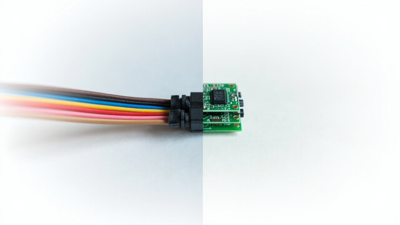
What Is a Wire-to-Board (WTB) Connector?
A wire-to-board connector terminates an insulated wire or cable to a printed circuit board. The wire side is usually a crimp or IDC housing with discrete contacts; the board side is a through-hole or SMT header soldered to the PCB.
WTB is the default choice whenever one side of the connection is a discrete wire rather than another PCB. Power inputs, sensor leads, panel-mount interfaces, battery connections, and most external I/O are WTB.
Common WTB families in our catalog:
- Wire-to-Board Connectors — the general category
- Power Wire-to-Board — high-current WTB for power inputs
- PCB Terminal Blocks — screw-clamp WTB for serviceable connections
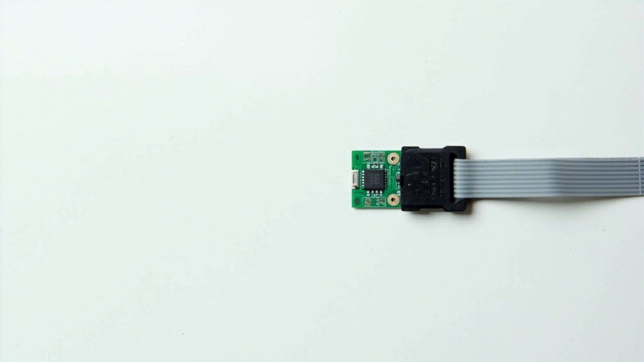
- IDC Connector — Insulation-Displacement WTB for ribbon cable
Key characteristics:
- Discrete wire side: easy to field-replace, serviceable
- Board side: header soldered once at PCB assembly
- Typically lower pin count (1–40 positions)
- Mating cycle: 10–50 cycles typical (not designed for repeated mating)
What Is a Board-to-Board (BTB) Connector?
A board-to-board connector mates two PCBs directly, with no cable in between. Both halves are soldered to their respective boards, and the connection is made by plugging one board onto the other.
BTB is the answer when two PCBs need to talk to each other inside the same enclosure. Display boards plugging into mainboards, sensor modules plugging into carrier boards, and daughter cards stacking onto baseboards are all BTB.
Common BTB families in our catalog:
- Board-to-Board Connectors — the general category
- Board Stacking Connectors — parallel stacking at a defined height
- Mezzanine Connectors — sub-category of stacking at specific heights
Key characteristics:
- Both sides: headers/receptacles soldered to PCBs
- No cable, no crimping, no field termination
- Higher pin counts (10–200+ positions)
- Mating cycle: 30–100+ cycles typical, designed for assembly-line mating
Side-by-Side Comparison
| Attribute | Wire-to-Board (WTB) | Board-to-Board (BTB) |
|---|---|---|
| What it joins | Wire/cable ↔ PCB | PCB ↔ PCB |
| Field serviceable | Yes (unplug, re-crimp) | No (de-solder to replace) |
| Pin count range | 1–40 typical | 10–200+ typical |
| Pitch range | 1.0mm – 10.0mm | 0.4mm – 5.0mm typical |
| Assembly cost | Lower (no cable assembly) | Lowest (just PCB headers) |
| Mating cycles | 10–50 | 30–100+ |
| Current rating | Up to 16A+ (with PCB terminal blocks) | Up to 5A typical (high-current variants exist) |
| Signal integrity | Limited by cable length | Excellent at short distances |
| High-speed data | Not ideal beyond USB 2.0 / SPI | Can support PCIe, MIPI, USB 3.x |
| Cost per mated pair | $0.05 – $2.00 | $0.10 – $5.00+ |
| Best for | Power, I/O, sensor leads, serviceable connections | Internal stacking, high-density signal, modular design |
The 4-Question Decision Flowchart
If you’re in a design review and need to pick fast, walk through these four questions in order:
1. Is one side of the connection a discrete wire (not a PCB)?
- Yes → WTB. You’re done.
- No (both sides are PCBs) → Go to Q2.
2. Do you need the connection to be field-serviceable?
- Yes → WTB is the only option (BTB requires de-soldering).
- No → Go to Q3.
3. Do the two PCBs sit at a fixed, defined spacing inside one enclosure?
- Yes → BTB with a fixed stack height. Use Board Stacking Connectors.
- No, they need to float/articulate → BTB with floating contacts (a BTB sub-family designed for misalignment tolerance).
- No, they need to be parallel but at a specific low height → Mezzanine Connectors.
4. Does the connection carry high-speed signals (above ~1 Gbps)?
- Yes → BTB is strongly preferred. Cable assemblies introduce SI loss and reflection; BTB preserves signal integrity.
- No, it’s power or low-speed signal → Either works; pick by serviceability, pin count, and cost.
Default if you’re stuck: If the two PCBs are inside the same sealed enclosure and not user-serviceable, BTB is almost always the right answer. If there’s a cable between them, WTB is the only answer.
Real Application Examples
Example 1: Industrial Sensor Module
A sensor module sits on top of a control board, separated by 8mm of standoffs, no field service expected. → BTB Mezzanine (parallel, fixed 8mm height).
Example 2: Washing Machine Control Panel
A user-replaceable control panel connects to the main PCB via a 6-pin cable harness. → WTB (the user pulls the panel, the cable unplugs).
Example 3: EV Battery Management
A BMS board connects to a master controller board across an 80mm air gap with a high-current cable. → Power WTB (terminal block style) on the controller side, cable lug on the BMS side.
Example 4: Consumer Wearable Display
A tiny display board mates to the mainboard at a 3mm stack height, no service expected, high-density signal. → BTB Board Stacking at 3mm height.
Common Mistakes That Force a Redesign
Mistake 1 — Spec’ing a BTB when the harness team needs a cable.
You save 3 cents per unit on the connector, but the harness team can’t build the assembly without crimping tooling. Result: production line stop. Fix: Always involve the harness / assembly team in connector selection.
Mistake 2 — Spec’ing a WTB when the boards are right next to each other.
You add cable assembly cost, EMI vulnerability, and a potential failure point — for no mechanical benefit. Fix: If the boards are <50mm apart and in the same enclosure, BTB is usually cheaper end-to-end.
Mistake 3 — Ignoring mating cycle ratings.
A WTB connector rated for 30 cycles gets plugged and unplugged 200 times in the field. Pins wear out. Connector fails. Fix: Check the mating cycle spec against the expected service life.
Mistake 4 — Mixing WTB and BTB pin counts in the same BOM.
The pick-and-place machine needs different feeders; the assembly team needs different tools. Consolidate.
Mistake 5 — Forgetting creepage and clearance for high-voltage WTB.
PCB terminal blocks at 300V need a minimum PCB cutout and trace clearance. Spec the connector first, lay out the board around it — not the other way around.
How to Spec It in Your RFQ
When you send an RFQ, include these five fields to get a fast, accurate quote:
- Topology: WTB or BTB (with sub-type: WTB-crimp, WTB-IDC, BTB-stacking, BTB-mezzanine)
- Pin count and pitch
- Current and voltage per circuit
- Mating cycle requirement (e.g., “30 cycles minimum”)
- Certifications (cULus, UL, CE, RoHS, REACH — see our UL vs cULus guide for cert specifics)
If you send that with your drawing, GSCONN can usually quote a matching part from stock within 24 hours.
FAQ
Q: Can a WTB connector carry high-speed signals like USB 3.0?
A: Generally no. Cable introduces too much loss and skew. For high-speed, use BTB or a dedicated high-speed cable assembly (e.g., USB-C, HDMI, MIPI).
Q: What’s the difference between a board stacking connector and a mezzanine connector?
A: “Mezzanine” is a marketing term for BTB connectors at a specific low stack height (typically 5–20mm). “Board stacking” is the broader category covering any parallel PCB-to-PCB. In practice, the two terms overlap; check the spec sheet for actual stack height and pin count.
Q: Can I use a BTB connector with a cable?
A: Not recommended. BTB headers aren’t designed for the mechanical stress of cable flex. Use a WTB or a proper cable assembly connector.
Q: How do I know if I need a “floating” BTB connector?
A: If the two PCBs are mated by hand or by a robot with limited placement accuracy (>0.5mm tolerance), you need floating contacts to absorb misalignment. Rigid BTB connectors require precise placement.
Q: For an outdoor application, is WTB or BTB better?
A: It depends on the enclosure. If the connector is inside a sealed enclosure, either works — but use conformal coating on BTB headers. If the connector is exposed to the elements, you need a waterproof WTB or a sealed BTB with an IP-rated mating face. Our Waterproof Connectors category covers the latter.
Conclusion
The wire-to-board vs board-to-board decision is one of the highest-leverage choices in any PCB design. Get it right early, and the rest of the assembly, harness, and service strategy follows. Get it wrong, and you’re looking at a redesign that costs weeks.
Key takeaways:
1. Wire on one side → WTB. PCB on both sides → BTB. That’s the 80% rule.
2. Field-serviceable is non-negotiable — if yes, WTB is the only option.
3. High-speed signal or short PCB-to-PCB distance → BTB is cheaper end-to-end, not just per connector.
4. Spec the connector first, then lay out the board around it — not the other way around.
Need a part recommendation? Send us your topology, pin count, and current requirement and we’ll match you to a GSCONN part from stock.
About the Author: GSCONN Engineering Team has supported 5,000+ connector selections across consumer, industrial, and automotive applications. We help engineers make the WTB/BTB call before the layout is locked, not after.
Related reading: UL vs cULus Certified Terminal Blocks — the certification guide for North American sourcing.