
Right Angle USB Connector: When and Why to Use It
Right Angle USB Connector: When and Why to Use It
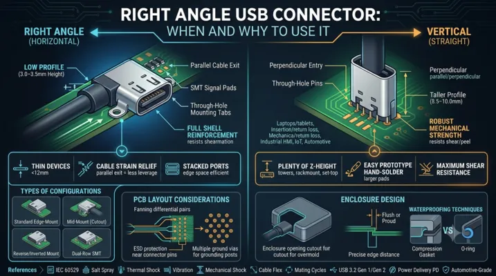
Space-constrained designs demand connectors that bend — literally. Here is when a right-angle USB connector is the right call, and when it creates more problems than it solves.
Table of Contents
- What Is a Right Angle USB Connector
- When to Choose Right Angle Over Vertical
- Types of Right Angle Configurations
- PCB Layout Considerations
- Signal Integrity at 90 Degrees
- Mechanical Stress and Reinforcement
- Enclosure Design with Right Angle Connectors
- Application-Specific Recommendations
- Cost and Availability
- FAQ
What Is a Right Angle USB Connector
A right angle USB connector mounts the receptacle so the cable inserts parallel to the PCB surface rather than perpendicular to it. In the component catalog, you will see these labeled as “right angle,” “horizontal,” or “90°” variants. The alternative is a vertical (straight) connector where the cable inserts at 90° to the board.
The defining characteristic: the connector body sits at the edge of the PCB (or in a cutout), and the mating axis runs along the board plane. This reduces the total height of the assembly — critical in products where every millimeter of thickness matters.
Right Angle vs Vertical: The Visual Difference
| Property | Right Angle | Vertical |
|---|---|---|
| Cable insertion direction | Parallel to PCB | Perpendicular to PCB |
| Height above PCB | 3.0–3.5 mm | 8.5–10.0 mm |
| PCB real estate | Connector depth into board: 7–9 mm | Connector footprint: ~8.5 × 7.5 mm |
| Typical use | Laptops, tablets, edge I/O | Desktop towers, set-top boxes, hubs |
| Mechanical stress on PCB | Shear + moment from cable leverage | Primarily through-hole shear |
When to Choose Right Angle Over Vertical
The decision tree is straightforward:
Choose Right Angle When:
-
Height is your primary constraint. If your enclosure is thinner than ~12 mm, a vertical USB connector will not fit. Right angle brings the connector height down to ~3.5 mm plus PCB thickness.
-
The connector is on the edge of the enclosure. Edge-mounted I/O naturally favors right-angle connectors because the cable exits parallel to the device surface. This is the standard laptop configuration.
-
Cable strain relief matters. A right-angle connector routes the cable along the device body, reducing the lever arm that would otherwise stress the connector when the cable is pulled. Vertical connectors concentrate all cable force on a small footprint.
-
You need multiple stacked ports. Side-by-side right-angle connectors occupy minimal board edge space. A typical laptop can fit two USB-C ports plus HDMI in a 50 mm edge span.
Choose Vertical When:
-
You have plenty of Z-height. Desktop towers and rack-mount equipment have 40 mm+ of internal clearance — vertical connectors simplify PCB routing by keeping signals on the top layer.
-
You need maximum mechanical strength. Vertical through-hole connectors are inherently stronger because the cable pull force translates to pin shear rather than peel — and solder joints resist shear far better than peel.
-
The connector is on the top surface of the enclosure. Set-top boxes, test instruments, and industrial panels often have top-facing ports. A vertical connector aligns naturally with this orientation.
-
You are hand-soldering prototypes. Vertical through-hole connectors are far easier to hand-solder than fine-pitch SMT right-angle connectors.
Types of Right Angle Configurations
Standard Edge-Mount
The connector body extends to the PCB edge, with SMT signal pads on the top (or bottom) surface and through-hole mounting tabs. This is the most common configuration.
Key dimensions:
– Body depth (into PCB): 6.5–9.0 mm
– Height above PCB: 3.0–3.5 mm
– PCB edge to connector centerline: 1.5–2.0 mm
Reverse / Inverted Mount
The connector is mounted on the bottom side of the PCB, with the receptacle opening facing upward through a PCB cutout. This is used when you need the connector on the opposite side of the board from the main components.
Critical consideration: The PCB cutout must precisely match the connector tongue position. A 0.3 mm misalignment means the cable plug scrapes against the PCB edge during insertion.
Mid-Mount (Board Cutout)
The connector sits inside a rectangular cutout in the PCB, with the receptacle opening flush with the board edge. This configuration is common in ultra-thin laptops where every fraction of a millimeter counts.
PCB thickness compatibility: Most mid-mount connectors are designed for 0.8 mm or 1.0 mm boards. Verify compatibility before committing.
Dual-Row SMT
Some high-density connectors use two rows of SMT pads (top and bottom of PCB) for the signal pins, eliminating through-hole tabs entirely. This enables single-pass reflow but sacrifices mechanical strength.
Pull force: Typically 20–40 N — about half of a through-hole hybrid design. Adequate for consumer devices where the connector is not expected to withstand abuse, but risky for industrial or automotive.
PCB Layout Considerations
Footprint Placement
Right-angle connectors should be placed at the PCB edge with the connector body extending to (or slightly beyond) the board outline. The mechanical drawing will specify the exact offset.
Critical dimensions to verify:
| Dimension | Typical Value | Tolerance | Why It Matters |
|---|---|---|---|
| Connector body overhang | 0–1.0 mm beyond PCB edge | ±0.1 mm | If the connector is recessed, the cable will not fully seat |
| Mounting tab hole diameter | 0.9–1.1 mm | ±0.05 mm | Too tight = assembly issues; too loose = weak joint |
| SMT pad length | 1.5–2.5 mm | ±0.1 mm | Too short = insufficient solder fillet; too long = tombstoning risk |
| Keep-out zone behind connector | 5–8 mm from board edge | — | Cable overmold clearance |
Routing Constraints
The signal pins on a right-angle USB-C connector exit the back of the connector body on a 0.5 mm pitch. You have approximately 3–4 mm of routing space before the signals must fan out to wider traces.
Routing strategy for USB 3.2 and above:
1. Route the SuperSpeed differential pairs first — they have the tightest constraints
2. Keep the TX and RX pairs on the same layer; avoid vias within 5 mm of the connector
3. Place ESD protection diodes within 10 mm of the connector pins
4. Route CC and SBU lines last — they are low-speed and tolerant of longer paths
Grounding
Right-angle connectors typically have two or four grounding posts. Four-post designs provide better EMI performance because they create a more complete ground ring around the signal pins. If EMI is a concern (USB 3.2 or above), prefer four-post designs and connect all posts directly to the PCB ground plane with multiple vias per post.
Signal Integrity at 90 Degrees
The right-angle bend inside the connector body creates an impedance discontinuity. In a straight connector, the signal path from the PCB pad through the contact to the mating interface is a straight line. In a right-angle connector, the signal must make a 90° turn inside the connector body.
Measured Impact
For USB 3.2 Gen 2 (10 Gbps) signals, a well-designed right-angle USB-C connector introduces:
| Parameter | Straight Connector | Right Angle Connector | Specification Limit |
|---|---|---|---|
| Insertion loss at 5 GHz | -0.8 dB | -1.2 dB | -2.0 dB |
| Return loss at 5 GHz | -18 dB | -14 dB | -12 dB |
| Differential impedance | 85Ω ± 5Ω | 85Ω ± 8Ω | 85Ω ± 10Ω |
| Near-end crosstalk | -40 dB | -35 dB | -30 dB |
These numbers are well within USB 3.2 specification limits. The right-angle penalty is real but manageable for 10 Gbps operation.
USB4 (40 Gbps) Considerations
At 40 Gbps, the signal wavelength in the connector is approximately 5 mm — comparable to the length of the right-angle bend itself. The impedance discontinuity becomes more significant. For USB4 designs:
- Request S-parameter data from the connector manufacturer. Look for insertion loss < -1.5 dB at 10 GHz and return loss < -10 dB.
- Simulate the full channel. Include the connector model, PCB traces, and cable in your simulation. Do not evaluate the connector in isolation.
- Consider a vertical connector if signal integrity margins are tight. The straight signal path eliminates one variable from an already challenging design.
Mechanical Stress and Reinforcement
Right-angle connectors experience fundamentally different stress patterns than vertical connectors.
Failure Modes
| Failure Mode | Root Cause | Prevention |
|---|---|---|
| SMT pad lift | Repeated cable insertion peels pads off PCB | Through-hole mounting tabs, larger SMT pad area |
| Solder joint crack | Thermal cycling + mechanical stress | Flexible termination design, adequate solder volume |
| Tongue fracture | Cable side-load bends the center tongue | Stainless steel tongue stiffener, full-perimeter shell |
| Shell deformation | Cable yanked at an angle deforms the shell opening | Thicker shell material (0.3 mm minimum), reinforced shell design |
Reinforcement Strategies
Through-hole mounting tabs are the first line of defense. Two tabs are standard; four tabs provide significantly better retention. The tab diameter (typically 0.8–1.2 mm) determines the solder joint cross-sectional area. Going from 0.8 mm to 1.0 mm increases shear area by 56%.
Additional PCB anchors: Some connectors include large SMT anchor pads on the sides of the body that are soldered to the PCB for additional mechanical support. These are not electrically connected — they exist purely for mechanical retention.
Underfill / staking: For high-reliability applications (automotive, aerospace), apply a small bead of epoxy underfill beneath the connector body after soldering. This distributes mechanical stress across the entire connector footprint rather than concentrating it at the mounting tabs.
Enclosure Design with Right Angle Connectors
The Opening Cutout
The enclosure cutout for a right-angle USB-C connector must accommodate both the connector shell and the cable plug overmold. The USB-C plug shell is 8.34 mm wide × 2.56 mm high, but the overmold is typically 11–13 mm wide × 6–8 mm high.
Minimum recommended cutout dimensions:
– Width: 12.0 mm (provides 1.5 mm clearance per side for the overmold)
– Height: 8.5 mm (provides clearance for angled cable insertion)
– Depth from PCB edge: Connector body overhang + 0.5 mm
Edge Distance
The connector centerline must be positioned at a precise distance from the PCB edge. For standard horizontal right-angle connectors, the PCB edge to connector centerline is typically 1.60–1.90 mm. If the enclosure wall thickness is 1.5 mm and the connector centerline is at 1.75 mm from the PCB edge, the connector face will sit 0.25 mm proud of the enclosure outer surface — close to flush.
Waterproofing at the Enclosure Interface
If you need IP-rated protection, the seal must be at the enclosure opening, not at the connector itself (unless using a sealed connector). Common approaches:
- Compression gasket: A die-cut silicone gasket compressed between the connector shell flange and the enclosure inner wall. Requires 15–25% compression for effective sealing.
- O-ring on connector: Some right-angle connectors include an O-ring groove on the front face. The O-ring seals against the enclosure wall when the PCB is mounted.
- Potting: Fill the gap between the connector body and the enclosure opening with a UV-curable adhesive. Effective but not serviceable.
Application-Specific Recommendations
Laptops and Tablets
Configuration: Right-angle SMT + TH hybrid, 24-pin, USB4-capable
Key requirements: 10k mating cycles, 5A current rating, stainless steel shell
Recommended shell height: 3.0–3.2 mm above PCB (thin enclosure)
Additional: Full-perimeter grounding, four-post mounting
Industrial HMIs and Panel PCs
Configuration: Right-angle TH hybrid, 12–16 pin, USB 3.2 Gen 1
Key requirements: IP65 front panel seal, extended temperature range (-40 to +85°C), 20k cycles
Recommended shell height: 3.2–3.5 mm (standard enclosure wall thickness)
Additional: O-ring seal on connector face, stainless steel shell
IoT Sensors and Edge Devices
Configuration: Right-angle SMT, 6–12 pin, USB 2.0
Key requirements: IP67, 5k cycles, 3A current rating
Recommended: Gasket-sealed receptacle with spring-loaded shutter
Additional: Overmolded cable assembly supplied with the device
Automotive Infotainment
Configuration: Right-angle TH hybrid, 12–16 pin, USB 3.2 Gen 1
Key requirements: AEC-Q200 qualification, -40 to +105°C, 10k cycles
Recommended: Stainless steel shell, 30μ” gold contacts, four-post mounting
Additional: EMI grounding fingers, underfill epoxy for vibration resistance
Cost and Availability
Price Ranges (1k volume, 2024)
| Type | Price Range (USD) | Lead Time |
|---|---|---|
| Basic right-angle SMT, 6-pin, USB 2.0 | $0.15–0.40 | 4–8 weeks |
| Right-angle hybrid, 16-pin, USB 3.2 | $0.60–1.20 | 6–12 weeks |
| Right-angle hybrid, 24-pin, USB4 | $1.00–2.50 | 8–16 weeks |
| Right-angle IP67, 12-pin | $2.00–4.00 | 10–20 weeks |
| Automotive-grade right-angle, 16-pin | $2.50–5.00 | 12–26 weeks |
Major Manufacturers
| Manufacturer | Strengths | Notable Series |
|---|---|---|
| Molex | Broad portfolio, USB4-certified options | 105450, 105455 |
| Amphenol ICC | High-reliability, IP-rated variants | 10157044, 10159525 |
| TE Connectivity | Automotive-grade, wide temp range | 2305018, 2342890 |
| JAE | Compact mid-mount designs | DX07 series |
| Hirose | Ultra-thin mid-mount, high cycle life | CX90MW series |
| GCT (Global Connector Technology) | Cost-competitive, fast samples | USB4155, USB4200 |
FAQ
Q: Can I use a standard vertical connector footprint and bend the pins to make it right-angle?
No. This is a common prototyping shortcut that creates reliability problems. The pin bending radius is uncontrolled, the plating cracks at the bend point, and the connector height becomes inconsistent. Use a connector designed as right-angle from the start.
Q: Do right-angle USB-C connectors have worse EMI than vertical?
Marginally. The 90° bend creates a small impedance discontinuity that generates slightly more radiation. In practice, the difference is 2–3 dB in near-field emissions — significant enough to matter if you are already close to regulatory limits, but not a dealbreaker for most designs.
Q: What is the minimum PCB thickness for a mid-mount right-angle connector?
0.6 mm is the practical minimum. Below that, the board is too flexible and the connector will rock during insertion. Most mid-mount connectors are optimized for 0.8 mm or 1.0 mm boards.
Q: Can I reflow a right-angle connector with through-hole tabs in a single pass?
Yes, using pin-in-paste (intrusive reflow). The through-hole tabs are printed with solder paste through the stencil, and the entire connector goes through reflow. The challenge is getting sufficient paste volume into the through-holes — you may need step stencil or overprinting. Wave soldering the tabs as a secondary step is more reliable but adds process cost.
Q: How do I handle the gap between the connector and the enclosure for ESD protection?
The connector shell should make electrical contact with the enclosure through conductive gaskets or spring fingers. This creates a Faraday cage that routes ESD strikes to chassis ground before they reach the PCB. If the enclosure is plastic, add a metal shield frame around the connector opening connected to PCB ground.
This article is part of the USB Connector Technical Series. For related topics, see our guides on USB Connector for PCB: Design Guidelines, USB Locking Connectors, and How to Choose the Right USB Type-C Connector.