
How to Choose the Right USB Type-C Connector for Your PCB
How to Choose the Right USB Type-C Connector for Your PCB
A systematic selection guide covering 14 parameters every hardware engineer should evaluate before committing to a USB-C connector.
Table of Contents
- Why USB-C Connector Selection Matters
- The 14-Parameter Selection Framework
- Mounting Type: The First Decision
- Pin Count and Protocol Support
- Current Rating and Power Delivery
- Mating Cycles and Mechanical Life
- Ingress Protection: Water and Dust
- Shell Material and Plating
- Operating Temperature Range
- Orientation: Vertical vs Horizontal vs Mid-Mount
- Certification and Compliance
- Selection Decision Matrix
- Common Selection Mistakes
- FAQ
Why USB-C Connector Selection Matters
Pick the wrong USB-C connector and you are not swapping a resistor — you are re-spinning a PCB, possibly retooling an enclosure, and burning 6–8 weeks of schedule. The USB-C connector is one of the few components on your board that touches both the electrical domain (signal integrity, power delivery) and the mechanical domain (enclosure fit, drop resistance, user ergonomics). Get either half wrong and the product fails.
Yet most engineers spend more time choosing an LDO than choosing their USB connector. That is the problem this guide aims to fix.
What Is at Stake
| If You Choose Wrong | Consequence |
|---|---|
| Undersized current rating | Connector overheats at full PD load, melts housing |
| Wrong pin count | Missing CC/SBU lines, USB PD or Alt Mode broken |
| Insufficient mating cycles | Connector wears out before product EOL |
| No IP rating in outdoor product | Corrosion within 3 months of field deployment |
| Wrong shell material | Galvanic corrosion when mated with customer cables |
| Non-USB-IF-certified part | Interop failures with major-brand cables and chargers |
| Wrong orientation | PCB-to-enclosure gap mismatch, mechanical interference |
The USB-C connector market is fragmented. Molex, Amphenol, TE, JAE, Hirose, and a dozen Shenzhen manufacturers all make “USB-C connectors” — but a Molex 105450-series and a no-name $0.03 part are not interchangeable. The difference shows up in the field, not on the schematic.
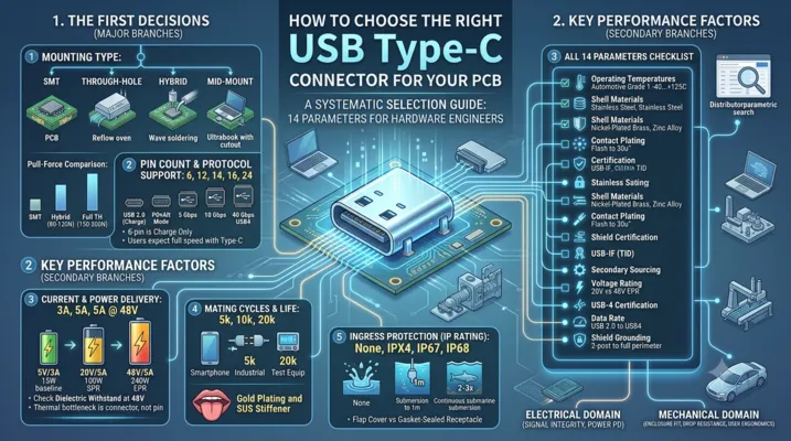
The 14-Parameter Selection Framework
Before you open a distributor’s parametric search, know what you need. Here is the checklist:
| # | Parameter | Example Values | Why It Matters |
|---|---|---|---|
| 1 | Mounting type | SMT, through-hole, hybrid, mid-mount | Determines PCB layout and assembly process |
| 2 | Pin count | 6, 12, 14, 16, 24 | Dictates protocol support (USB 2.0 vs USB 3.2 vs USB4) |
| 3 | Orientation | Horizontal, vertical, mid-mount | Affects enclosure design and cable routing |
| 4 | Current rating | 3A, 5A | Must match your PD power budget |
| 5 | Voltage rating | 20V, 48V | EPR (48V) requires higher dielectric withstand |
| 6 | Data rate support | USB 2.0, 5 Gbps, 10 Gbps, 40 Gbps | Determines if USB 3.2 or USB4 is possible |
| 7 | Mating cycles | 5k, 10k, 20k | Consumer vs industrial life requirement |
| 8 | IP rating | None, IP67, IP68 | Outdoor/industrial environments |
| 9 | Shell material | Stainless steel, nickel-plated brass, zinc alloy | Corrosion resistance, EMI shielding |
| 10 | Contact plating | Gold flash, 15μ” Au, 30μ” Au | Contact resistance over life |
| 11 | Operating temp | -40 to +85°C, -40 to +105°C | Automotive and outdoor applications |
| 12 | Shield grounding | 2-post, 4-post, full perimeter | EMI performance |
| 13 | USB-IF certification | TID assigned | Interoperability guarantee |
| 14 | Secondary sourcing | Single-source vs multi-source | Supply chain resilience |
Work through these in order. The first three (mounting, pin count, orientation) lock your PCB footprint. The rest determine whether the connector survives in your target environment.
Mounting Type: The First Decision
Surface Mount (SMT)
SMT USB-C connectors dominate consumer electronics for good reason: they enable single-sided reflow, save board space, and support high-density layouts.
Typical footprint: 8.3 mm × 7.5 mm (horizontal), with 0.5 mm pitch on the signal row.
Key considerations:
– Signal pins use 0.5 mm pitch — fine but manageable with standard PCB tolerances
– Mounting tabs are the primary mechanical anchor; choose parts with at least 4 through-hole or large SMD tabs
– Co-planarity of 0.10 mm max across all pins is critical — if your PCB has any warpage, you will see open joints
Best for: Laptops, tablets, smartphones, dongles, consumer devices where reflow is the only assembly step.
Through-Hole
Through-hole USB-C connectors use 0.8–1.0 mm diameter pins that penetrate the PCB and are wave-soldered from the bottom. They sacrifice density for mechanical strength.
Pull-force comparison (typical values):
– SMT-only: 30–50 N before connector separates from board
– Through-hole hybrid (TH mounting tabs + SMT signals): 80–120 N
– Full through-hole: 150–200 N
Best for: Industrial equipment, automotive ECUs, test instruments, any application where the cable will be yanked regularly.
Mid-Mount (Reverse Mount)
Mid-mount connectors sit in a PCB cutout, with the receptacle opening on the opposite side of the board from where the pins are soldered. This is the go-to for ultra-thin designs.
Critical dimension: The PCB thickness must match the connector’s “board thickness range” specification. Most mid-mount USB-C connectors accept 0.8 mm, 1.0 mm, or 1.2 mm boards. Using a 1.6 mm board with a 1.0 mm connector means the receptacle will sit 0.6 mm proud of the PCB surface — the cable will not fully insert.
Best for: Ultrabooks, thin tablets, wearables.
Hybrid
Hybrid connectors combine SMT signal pins with through-hole mounting tabs. This is the most common configuration in the market because it balances assembly efficiency (single reflow for all pins + tabs using pin-in-paste) with mechanical robustness.
Pin Count and Protocol Support
USB-C has 24 pins, but not all connectors populate all 24. The pin count you choose directly gates what your product can do.
| Pin Count | Populated Pins | Protocol Support | Typical Use Case |
|---|---|---|---|
| 6-pin | VBUS, GND, D+, D- | USB 2.0 only, no PD negotiation | Charging-only devices, simple peripherals |
| 12-pin | 6-pin + CC1, CC2, SBU1, SBU2 | USB 2.0 + PD + possible Alt Mode | Most mid-range consumer devices |
| 14-pin | 12-pin + one SuperSpeed pair | USB 3.2 Gen 1 (5 Gbps) + PD | External SSDs, cameras |
| 16-pin | 14-pin + second SuperSpeed pair | USB 3.2 Gen 2 (10 Gbps) + PD | Docking stations, monitors |
| 24-pin | Full pinout | USB4 (40 Gbps), all PD, all Alt Modes | High-end laptops, Thunderbolt docks |
The Hidden Cost of Fewer Pins
A 6-pin USB-C connector is physically compatible with a full-featured USB-C cable, but the user will not know that your device only supports USB 2.0 speeds. They will plug in a USB 3.2 drive, get 40 MB/s instead of 1,000 MB/s, and blame your product — not the cable. If your product has a USB-C port, users expect it to do everything a USB-C port can do. Violating that expectation without clear labeling creates support headaches.
Rule of thumb: If your product has a USB-C port and connects to a host that supports USB 3.x, use at minimum a 16-pin connector. Reserve 6-pin for dedicated charging ports or cost-sensitive IoT devices where data rate is irrelevant.
Current Rating and Power Delivery
USB-C connectors are rated by current per contact, and the rating is not the same for all pins. VBUS pins carry the power; the other 20 pins carry negligible current.
Standard Ratings
| USB PD Profile | Voltage | Current | Total Power | Required Connector Rating |
|---|---|---|---|---|
| USB 2.0 baseline | 5V | 500 mA | 2.5W | 1A minimum |
| BC 1.2 | 5V | 1.5A | 7.5W | 2A minimum |
| USB-C default | 5V | 3A | 15W | 3A minimum |
| USB PD 3.0 SPR | Up to 20V | 5A | 100W | 5A minimum |
| USB PD 3.1 EPR | Up to 48V | 5A | 240W | 5A at 48V |
What “5A Rating” Actually Means
A connector rated for 5A means each VBUS pin can carry 5A. USB-C has four VBUS pins (A4, A9, B4, B9), so the total current capacity across all VBUS pins is 20A — far more than any USB PD contract will use. The real bottleneck is not the pin itself but the contact interface and the thermal dissipation of the connector body.
Temperature rise at 5A (typical values for a mid-quality connector):
– 25°C ambient: 15–20°C rise at the contact interface
– 60°C ambient: 25–30°C rise, reaching 85–90°C at the contact
– Above 90°C, gold plating begins to degrade through accelerated diffusion
For EPR (48V) applications, verify the connector’s dielectric withstand voltage. The USB-C specification requires 100V minimum between VBUS and adjacent signal pins. Many connectors rated for 20V will arc at 48V if the creepage distance is insufficient.
Mating Cycles and Mechanical Life
USB-C was designed for 10,000 mating cycles minimum — but not every connector on the market actually achieves this.
| Application | Recommended Mating Cycles | Realistic Daily Usage | Expected Life at Rating |
|---|---|---|---|
| Smartphone | 10,000 | 2–3 plugs/day | 9–13 years |
| Laptop | 10,000 | 3–5 plugs/day | 5–9 years |
| Industrial sensor | 5,000 | 1 plug/month | 400+ years (cycle life is not the limiter) |
| Test equipment | 20,000 | 20–50 plugs/day | 1–3 years |
| Public kiosk/charging station | 20,000+ | 50–100 plugs/day | <1 year at 10k rating |
What Determines Mating Cycle Life
- Contact normal force: Higher force = better electrical contact but faster wear. USB-C targets 0.5–1.0 N per contact.
- Contact plating thickness: 30μ” gold lasts significantly longer than flash gold (3–5μ”). After 5,000 cycles, flash gold is largely gone, exposing nickel underplate.
- Tongue design: The center tongue (the part that breaks off if you look at it wrong) is the weakest point. Two-piece tongue designs (separate plastic + metal stiffener) outlast one-piece molded tongues.
- Spring contact geometry: Dual-beam contacts (two independent contact points per pin) provide redundancy and distribute wear.
How to verify: Ask the manufacturer for the IEC 60512-9-1 test report, not just the datasheet claim. A legitimate 10k-cycle part will have test data showing contact resistance <50 mΩ increase after 10,000 cycles.
Ingress Protection: Water and Dust
If your product goes outdoors, into a factory, or into a kitchen, you need an IP-rated USB-C connector. Standard consumer USB-C connectors have zero ingress protection — water flows straight through the receptacle opening onto the PCB.
IP-Rated USB-C Options
| IP Rating | Protection Level | Typical Implementation | Cost Premium vs Non-IP |
|---|---|---|---|
| IP67 | Immersion up to 1m for 30 min | Gasket-sealed receptacle + overmolded cable plug | 2–3× |
| IP68 | Continuous immersion beyond 1m | Fully potted rear, sealed mating face, custom cable assembly | 3–5× |
| IPX4 | Splash-resistant (all directions) | Rubber flap cover + basic gasket | 1.5–2× |
| IPX7 | Temporary immersion (same as IP67) | Same as IP67 but with more rigorous validation | 2–3× |
The Flap vs Gasket Trade-off
Rubber flap covers are cheap and easy, but they fail in two ways: users forget to close them, and the flap hinge fatigues after ~2,000 open/close cycles. Once the flap is open or broken, the connector has zero protection.
Gasket-sealed receptacles seal at the mating interface — the connector is protected even when no cable is plugged in. A spring-loaded shutter behind the gasket provides a secondary barrier. This approach costs more but survives real-world abuse.
Important: An IP-rated receptacle is useless without an IP-rated cable assembly. If your customer plugs in a standard USB-C cable, water enters through the cable connector. For true IP67/IP68 protection, you must supply a matched cable assembly with an overmolded plug that seals against the receptacle gasket.
Shell Material and Plating
The shell (outer metal housing) serves three functions: mechanical protection of the tongue, EMI shielding, and cable retention.
| Material | Pros | Cons | Typical Use |
|---|---|---|---|
| Stainless steel (SUS304) | Excellent corrosion resistance, high strength, no plating needed | Higher cost, heavier | Premium consumer, industrial, marine |
| Nickel-plated brass | Good conductivity, lower cost than SS | Nickel wears through after ~5k cycles exposing brass, which corrodes | Mid-range consumer |
| Zinc alloy (Zamak) | Low cost, die-castable to complex shapes | Brittle, poor corrosion resistance without coating | Ultra-low-cost chargers |
| Cold-rolled steel (SPCC) | Very low cost | Rusts if plating is scratched, poor EMI at high frequencies | Throwaway cables |
Galvanic Corrosion Warning
If your product has an aluminum enclosure and your USB-C connector shell is nickel-plated brass, the connector shell becomes the anode in a galvanic couple. In humid environments, the connector shell will corrode preferentially. This is why premium aluminum laptops use stainless steel USB-C connectors or isolate the connector shell from the chassis with a plastic frame.
EMI Performance
USB 3.2 Gen 2 and USB4 operate at 10–40 Gbps with fundamental frequencies in the GHz range. The connector shell must provide a low-impedance path to the PCB ground plane. Look for:
- Full-perimeter grounding: The shell should contact the PCB ground on all four sides, not just two mounting posts
- Grounding fingers: Spring contacts on the shell interior that mate with the cable plug shell
- Shell-to-PCB impedance: <0.5Ω at DC, <5Ω at 5 GHz
Operating Temperature Range
Standard consumer USB-C connectors are rated for -30 to +85°C. That covers 90% of applications. But if you are designing for automotive, outdoor industrial, or downhole equipment, you need extended temperature range.
| Temperature Grade | Range | Application |
|---|---|---|
| Commercial | 0 to +70°C | Indoor consumer electronics |
| Extended commercial | -30 to +85°C | Outdoor consumer, standard industrial |
| Industrial | -40 to +85°C | Factory automation, outdoor telecom |
| Automotive Grade 2 | -40 to +105°C | Passenger compartment electronics |
| Automotive Grade 1 | -40 to +125°C | Engine compartment, under-hood |
What Fails at Temperature Extremes
Low temperature: The plastic tongue becomes brittle. At -40°C, standard LCP (liquid crystal polymer) retains ~80% of its room-temperature strength, but some cheaper PBT-based tongues lose 50%+ and crack on insertion.
High temperature: Gold-nickel interdiffusion accelerates. At 105°C continuous operation, 15μ” gold over nickel can degrade to <5μ” effective gold within 2–3 years. For automotive applications, specify 30μ” gold minimum or palladium-nickel (PdNi) alloy contacts.
Orientation: Vertical vs Horizontal vs Mid-Mount
| Orientation | Board Space | Height Above PCB | Cable Direction | Best For |
|---|---|---|---|---|
| Horizontal (right-angle) | ~8.5 × 7.5 mm | ~3.2 mm | Parallel to board | Laptops, dongles, edge-mounted ports |
| Vertical (straight) | ~8.5 × 7.5 mm | ~9.5 mm | Perpendicular to board | Desktop towers, set-top boxes, test equipment |
| Mid-mount (reverse) | ~8.5 × 7.5 mm + cutout | ~1.5 mm above board | Parallel to board | Ultra-thin devices |
| Top-mount horizontal | ~8.5 × 7.5 mm | ~3.2 mm | Parallel, opposite side | Specific enclosure constraints |
The Enclosure Gap
This is the dimension that bites engineers. The distance from the PCB surface to the centerline of the USB-C opening in your enclosure must match the connector’s “PCB-to-center” height. For horizontal connectors, this is typically 3.10–3.30 mm. A 0.2 mm mismatch means the cable plug scrapes against the enclosure or does not fully seat.
Checklist before locking the footprint:
1. Get the mechanical drawing from the connector manufacturer (not the simplified datasheet drawing)
2. Add the PCB thickness to the connector height to get the total height above the enclosure mounting surface
3. Add your enclosure wall thickness and any gasket compression
4. Verify the gap on both sides of the connector (the plug overmold is wider than the metal shell)
Certification and Compliance
USB-IF Certification
A USB-IF certified connector has a TID (Test ID) assigned by an authorized test lab. The TID means the connector has passed:
– Mechanical tests (insertion force, extraction force, durability)
– Electrical tests (contact resistance, insulation resistance, dielectric withstand)
– Environmental tests (thermal shock, mixed flowing gas corrosion)
– Dimensional compliance (the USB-C mechanical spec is 400+ pages)
Why non-certified connectors fail: They often pass visual inspection and basic electrical tests but fail on dimensional tolerances. A tongue that is 0.05 mm too thick will damage the customer’s cable. A shell that is 0.1 mm too wide will not retain the cable securely.
Other Standards
| Standard | What It Covers | When Required |
|---|---|---|
| USB-IF Compliance | USB connector and cable interoperability | Any product using the USB logo |
| IEC 62680 | USB connectors for EU common charger regulation | Products sold in EU (mandatory from 2024) |
| UL 94 V-0 | Flammability of connector plastic | Any product seeking UL listing |
| RoHS / REACH | Hazardous substance restrictions | Products sold in EU |
| MIL-STD-202 | Shock, vibration, thermal shock | Military and aerospace |
Selection Decision Matrix
Use this matrix to narrow your choices. Start from the left column and work right.
| Application | Mounting | Pins | Current | IP | Cycles | Orientation | Shell Material | Temp Range |
|---|---|---|---|---|---|---|---|---|
| Smartphone charger port | SMT | 12–16 | 3A | None | 10k | Horizontal | SS | -30 to +85°C |
| Laptop USB-C port | SMT + TH tabs | 24 | 5A | None | 10k | Horizontal | SS | -30 to +85°C |
| Industrial IoT sensor | TH hybrid | 6–12 | 3A | IP67 | 5k | Horizontal | SS | -40 to +85°C |
| Automotive infotainment | TH hybrid | 12–16 | 5A | IP54 | 10k | Horizontal | SS | -40 to +105°C |
| Outdoor LED display | TH hybrid | 12 | 5A | IP67 | 5k | Vertical | SS | -40 to +85°C |
| Medical handheld device | SMT | 12 | 3A | IPX4 | 10k | Mid-mount | SS | -30 to +85°C |
| Test & measurement | TH | 24 | 5A | None | 20k | Vertical | SS | -30 to +85°C |
| Public charging kiosk | TH | 12–16 | 5A | IP54 | 20k+ | Vertical | SS | -40 to +85°C |
| Ultra-low-cost charger | SMT | 6 | 3A | None | 5k | Horizontal | Ni-brass | 0 to +70°C |
Common Selection Mistakes
Mistake 1: Choosing by Price Alone
A $0.03 USB-C connector exists for a reason — it is for disposable products where the connector only needs to work a few dozen times. The failure mode is not dramatic: contact resistance creeps up, the cable starts disconnecting intermittently, and your product gets returned. The BOM savings of $0.20 are wiped out by one RMA.
Mistake 2: Ignoring the Mechanical Drawing
The parametric search on Digi-Key or Mouser tells you pin count, orientation, and current rating. It does not tell you:
– Whether the mounting tabs are 0.8 mm or 1.0 mm diameter (your PCB hole must match)
– The exact height from PCB surface to connector centerline
– The recommended PCB cutout dimensions for mid-mount parts
– The keep-out zone around the connector for the cable plug overmold
Always download the full mechanical drawing before placing the footprint.
Mistake 3: Assuming All 24-Pin Connectors Support USB4
A 24-pin connector has all 24 pins physically present, but the internal construction determines signal integrity. USB4 at 40 Gbps requires the connector to maintain 85Ω differential impedance through the entire signal path with <0.5 dB insertion loss at 10 GHz. Many 24-pin connectors designed for USB 3.2 (10 Gbps) will fail USB4 compliance due to excessive crosstalk between the SuperSpeed pairs. Check the manufacturer’s S-parameter data if you are targeting USB4.
Mistake 4: Forgetting the Cable Overmold
The USB-C plug has an overmolded strain relief that extends approximately 6–8 mm beyond the metal shell. If you place components, mounting bosses, or enclosure walls within this zone, the cable will not fully insert. Reserve a 10 mm × 12 mm keep-out zone centered on the connector opening.
Mistake 5: Single-Sourcing Without a Drop-In Replacement
If you design your PCB footprint for a Molex 105450-0101 and Molex discontinues it or has a 26-week lead time, you are stuck. Before finalizing the footprint, identify at least one drop-in compatible part from another manufacturer (Amphenol, TE, JAE, or Hirose). Verify that the footprint, height, and keep-out zones are truly identical — not just “similar.”
FAQ
Q: Can I use a 6-pin USB-C connector and still negotiate USB PD power contracts?
Yes. USB PD negotiation happens on the CC line, and a 6-pin connector does not include CC1/CC2. Without the CC pins, you default to USB-C baseline power: 5V at up to 3A if the Rp pull-up is correctly set on the receptacle side. You cannot negotiate higher voltages or currents without CC communication.
Q: What is the real-world insertion force for USB-C?
The USB-C specification defines insertion force as 5–20 N. Most quality connectors fall in the 8–12 N range. Below 5 N, the connector feels loose and may disconnect under cable weight. Above 20 N, users complain it is “hard to plug in” and may damage the PCB solder joints over repeated use.
Q: Do I need EMI grounding fingers on the connector shell?
For USB 2.0-only designs: not strictly necessary, but recommended. For USB 3.2 and above: yes, absolutely. The SuperSpeed differential pairs operate at 5–10 Gbps, and without proper shell grounding, the connector becomes an efficient antenna at these frequencies. You will fail radiated emissions testing.
Q: What is the difference between “short body” and “long body” USB-C connectors?
The body length (depth of the connector behind the PCB edge) affects how far the connector extends into your board. Short-body connectors are ~6.5 mm deep; long-body are ~8.5 mm. Short-body saves PCB real estate but typically has fewer and smaller mounting tabs, reducing mechanical strength.
Q: Can I use a USB-C connector rated for 20V in a 48V EPR design?
No. The creepage distance between VBUS and adjacent signal pins is designed for the rated voltage. At 48V, a connector rated for 20V may not have sufficient creepage to prevent arcing under humidity and contamination. This is a safety issue, not a performance issue.
Q: How do I verify that a connector is genuinely USB-IF certified?
Search the USB-IF Integrators List at usb.org. Enter the manufacturer name or TID. If the connector is not listed, it is not certified — regardless of what the datasheet says. Some manufacturers claim “designed to USB-IF standards,” which means nothing legally.
Q: What is the shelf life of a USB-C connector?
Unused connectors stored in controlled conditions (25°C, <60% RH, sealed packaging) have a shelf life of 12–24 months. After that, contact plating oxidation begins to increase contact resistance. Connectors with 30μ” gold plating age more gracefully than flash gold.
This article is part of the USB Connector Technical Series. For related topics, see our guides on USB PCB Design Guidelines, Waterproof USB Connectors, and USB 3.0 vs USB 3.1.