
When to Use a Stacked USB Connector: A Decision Guide for PCB and System Designers
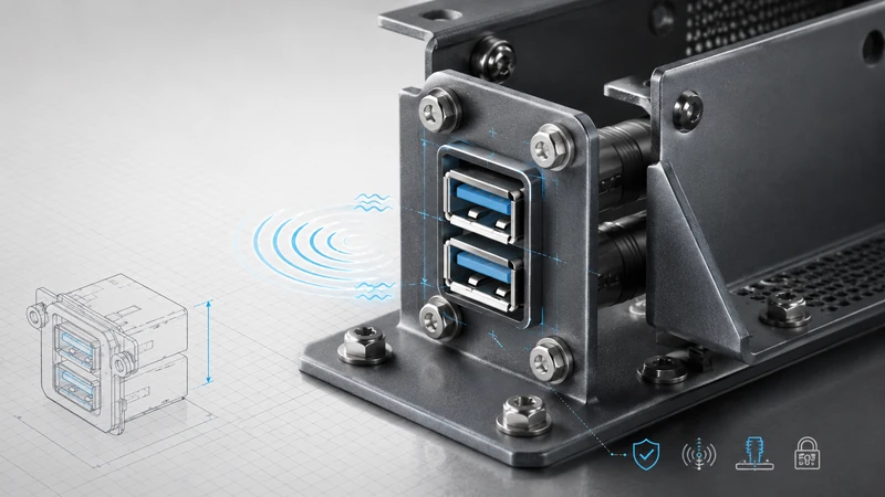
A stacked USB connector is the right answer when the product needs two accessible USB ports but does not have enough panel width for two separate connectors. It is the wrong answer when height, high-speed signal margin, frequent cable insertion, or high current is the real design constraint.
Use this guide during concept layout, before the PCB outline and enclosure panel are frozen.
Start with this decision path
Do you need two external USB ports in the same service area?
├─ No  → Use a single connector or move one port internally.
└─ Yes
   ├─ Is panel width tight? → Consider stacked.
   ├─ Is enclosure height tight? → Consider side-by-side.
   ├─ Is USB 3.x/10 Gbps margin critical? → Validate stacked early or use side-by-side.
   ├─ Is the port used often or under vibration? → Add bracket/panel support or use side-by-side.
   └─ Is sealing important? → Stacked can help by reducing panel openings.
1. Use stacked when panel width is the constraint
This is the strongest reason. In compact products, the I/O edge may need USB, Ethernet, power, LEDs, SIM access, antenna connectors, and labels. A stacked USB connector lets the design keep two ports without spending twice the width.
Good examples:
- industrial gateways and embedded PCs;
- 1U/2U server management panels;
- smart-building controllers;
- compact medical instruments;
- outdoor service ports where one sealed opening is preferred.
If the enclosure has plenty of width, stacked may not be worth the extra mechanical and sourcing considerations.
2. Use stacked confidently for USB 2.0 service ports
USB 2.0 is forgiving compared with USB 3.x. For keyboard, mouse, service console, firmware recovery, log export, and low-speed peripherals, a stacked connector usually gives the space benefit without a serious signal-integrity penalty.
Still follow normal layout practice: keep D+/D− controlled and short, avoid stubs, place ESD protection near the connector, and provide a sensible return path for the shield.
3. Use stacked carefully for USB 3.x
USB 3.x at 5 Gbps can work well through a shielded stacked connector, but the layout has less slack. The connector’s internal geometry, the upper-port routing, the shell connection, and cable quality all matter.
Use stacked USB 3.x when:
- the panel width saving is important;
- a shielded connector is available;
- the PCB can follow the recommended footprint;
- the cable length and quality are controlled;
- pre-compliance testing is planned.
Use side-by-side when the link budget is tight, the cable is long, the environment is noisy, or the design is targeting 10 Gbps and above without connector-specific SI data.
4. Avoid stacked when height is the problem
Stacked saves width by using height. That can be a problem in shallow enclosures, products with daughterboards above the I/O area, or handheld designs where the connector sits under a thin plastic wall.
Before choosing stacked, check the full 3D stack:
- connector body height;
- cable overmold height;
- finger clearance;
- panel wall thickness;
- dust cap or waterproof cap clearance;
- nearby heatsinks, boards, or brackets.
A connector that fits on the PCB may still fail in the enclosure.
5. Reinforce stacked connectors for field use
If users will plug and unplug cables often, or if the product vibrates, do not leave a stacked connector unsupported at the PCB edge. The upper port creates leverage during insertion.
Use at least one of the following:
- through-hole shell stakes;
- a connector body bracket;
- a nearby PCB mounting screw;
- a panel-mount connector;
- cable strain relief.
For equipment that ships with a cable permanently connected, strain relief is not optional. The cable is part of the mechanical system.
6. Use stacked when sealing benefits matter
For IP-rated equipment, fewer panel openings usually means fewer sealing problems. A stacked connector with one gasketed opening can be easier to validate than two separate cutouts.
However, do not confuse a sealed connector with a sealed product. The panel cutout, gasket material, screw torque, mating cable, cap, and enclosure flatness all determine the final result.
7. Cost decision: look beyond connector price
A stacked connector often costs more than a single connector pair, but it may reduce total product cost by saving panel space, reducing cutouts, simplifying gaskets, or allowing a smaller PCB outline.
Use a product-level cost comparison:
| Cost item | Why it matters |
|---|---|
| Connector price | Stacked may be higher. |
| PCB outline | Smaller width can reduce board cost or enable a smaller enclosure. |
| Panel machining | One cutout may be cheaper than two. |
| Gasket and seal | One sealing area can reduce parts and assembly time. |
| Second sourcing | Side-by-side often has more alternate options. |
| Rework | Stacked may be harder to inspect and replace. |
8. Application recommendations
Industrial PC or gateway
Use stacked when the I/O panel is crowded and USB is primarily service, logging, or accessory use. Add through-hole retention and consider locking cables in vibration-prone installations.
Server management port
Stacked is often a good fit because panel width is limited and the port is usually not carrying a difficult high-speed channel. Label the ports clearly for service.
Consumer router or set-top box
Stacked can make sense for space and appearance, especially for USB 2.0. Keep cost and second-source options in mind.
Medical equipment
Use stacked when panel width and cleanability matter. Use shielded versions, cleanable materials, and documentation suitable for the device design file. Do not claim medical compliance based only on the connector.
Automotive or transportation
Use stacked only with mechanical support, cable retention, and environmental validation. Side-by-side may be safer if panel space allows.
9. Boundary cases worth discussing early
Some designs sit between the obvious answers. A gateway with one permanent modem cable and one service port may look like a stacked candidate, but the permanent cable needs strain relief and may block the service port. A small medical instrument may benefit from one sealed stacked opening, but a single Type-C port plus an internal service header may be cleaner if two external ports are not truly needed. A server may have enough PCB area but still choose stacked because the rear I/O shield is the limiting geometry.
These boundary cases should be resolved before the industrial design and PCB layout diverge. The connector decision affects the enclosure cutout, cable label, ESD location, board mounting, and purchasing alternates. Changing from stacked to side-by-side late in the project usually means redesigning the mechanical panel, not just swapping a footprint.
10. GSConn selection notes
For a GSConn stacked USB design, define the design driver first: width saving, USB speed, sealing, vibration, current, temperature, or documentation. Then request samples and drawings for the specific connector style. For USB 3.x, ask for layout guidance. For outdoor and high-vibration products, consider panel-mount or bracketed versions before the enclosure is finalized.
Final checklist
- [ ] Two external ports are truly required.
- [ ] Width saving is more valuable than the added height.
- [ ] USB speed and signal margin have been reviewed.
- [ ] Mechanical support is adequate for upper-port insertion force.
- [ ] The connector, cable, and enclosure fit together in 3D.
- [ ] Sealing claims are validated at the product level.
- [ ] Purchasing has checked lead time and alternates.