
USB PD Connector Requirements: 240W Guide
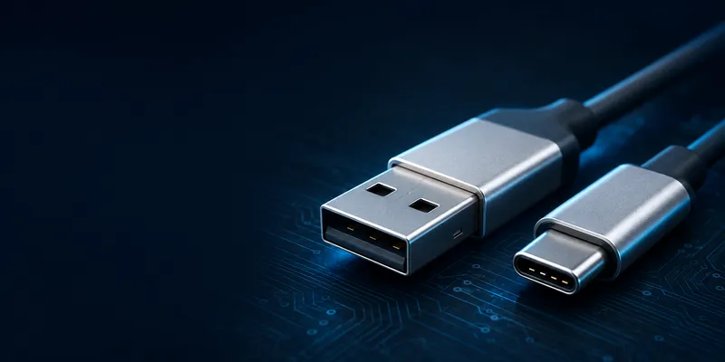
USB PD Connector Requirements: Type-C Power, EPR Cables and Validation
USB Power Delivery (USB PD) negotiates voltage and current over the USB Type-C Configuration Channel (CC). A connector’s shape or pin count is not enough to prove PD capability. The source, sink, cable, connector, protection circuit and thermal design must be compatible.
PD power ranges
| Power range | Typical voltage/current example | Key design point |
|---|---|---|
| Standard power range | 5 V, 9 V, 15 V or 20 V profiles | Confirm the required PDOs and cable current |
| SPR up to 100 W class | Up to 20 V × 5 A | 5 A cable identification and connector temperature matter |
| EPR up to 240 W | Up to 48 V × 5 A | EPR-capable source, sink, cable, protection and insulation are required |
USB-IF describes the USB PD 3.1 EPR range as extending power up to 240 W with additional fixed-voltage levels. The actual product power is limited by the negotiated profile and the lowest-rated component in the system.
How negotiation works
- The Type-C connection establishes orientation and source/sink roles through CC.
- The source advertises its supported Power Data Objects (PDOs).
- The sink requests a compatible voltage/current profile.
- The source accepts and transitions to the requested operating voltage.
- The devices may renegotiate as the load or battery state changes.
The default attach state is not permission to apply the highest voltage immediately. Implement the required protections and use a compliant PD controller and firmware strategy.
Connector requirements
For a Type-C PD design, specify more than “24-pin USB-C.” Define:
- CC1/CC2 routing and configuration components;
- VBUS and GND contact allocation;
- current rating at the intended temperature and mating condition;
- overvoltage, overcurrent, short-circuit and reverse-current protection;
- creepage, clearance and insulation requirements for higher-voltage EPR designs;
- connector orientation, mounting strength and cable retention;
- USB data, SuperSpeed and DisplayPort requirements, if any.
Reduced-pin Type-C connectors may support selected functions, but they may omit SuperSpeed or alternate-mode contacts. Confirm the actual pinout and the part’s electrical rating with the supplier.
Cable current and e-markers
| Cable capability | Typical planning limit | What to verify |
|---|---|---|
| 3 A cable | Up to 60 W at 20 V | Current marking and voltage drop |
| 5 A cable | Up to 100 W at 20 V | E-marker, conductor size and temperature rise |
| EPR cable | Up to 240 W at 48 V | EPR identification, insulation, construction and test evidence |
For USB-C currents above 3 A, the source must identify the cable capability through the required electronic marking mechanism. A cable may support high-speed data but only 3 A power, or 5 A power but USB 2.0 data. Treat data and power as independent selections.
PPS and charging behavior
Programmable Power Supply (PPS) allows a compatible sink to request a more closely controlled voltage rather than using only fixed levels. PPS performance depends on the charger, sink, PD controller, battery-management system and thermal limits. Do not promise faster charging from a connector alone.
Power and high-speed data on one cable
A Type-C cable can carry PD power while carrying USB data or an alternate mode, but not every cable supports every combination. The system requirement should list:
- maximum negotiated power;
- minimum data speed;
- DisplayPort or other alternate mode;
- cable length and passive/active construction;
- ESD and EMC requirements;
- allowable voltage drop and temperature rise.
Validation plan
- Test every advertised source/sink PDO and role-swap behavior.
- Verify attach, detach and cable orientation on both CC pins.
- Measure VBUS rise, overshoot, ripple and drop under load.
- Test short circuit, overcurrent, overtemperature and abnormal detach.
- Test the highest power with the final connector, cable and enclosure.
- Confirm the cable’s e-marker and advertised capability.
- Run ESD, vibration, mating-life and thermal cycling as required.
GSConn can review 24-pin and reduced-pin Type-C connector options for PD products. Request the exact part rating, contact temperature data, mating-cycle conditions, pin assignment and evidence supporting the required SPR or EPR application.
FAQ
Does a 5 A cable guarantee 100 W charging?
No. The source, sink, PD profile, connector, cable and thermal conditions must all support the requested power.
Does USB PD require USB 3.x data?
No. PD can operate with USB 2.0 data or a charge-only design, provided the Type-C power and CC implementation is correct.
Can any Type-C connector be used for 240 W?
No. Use a connector and complete system specifically evaluated for the intended EPR voltage, current, insulation and thermal requirements.
Related reading
Sources
Related reading on GSConn
GSConn application notes that complement this guide: