
Crimp vs IDC vs Solder: Wire Termination Methods Compared
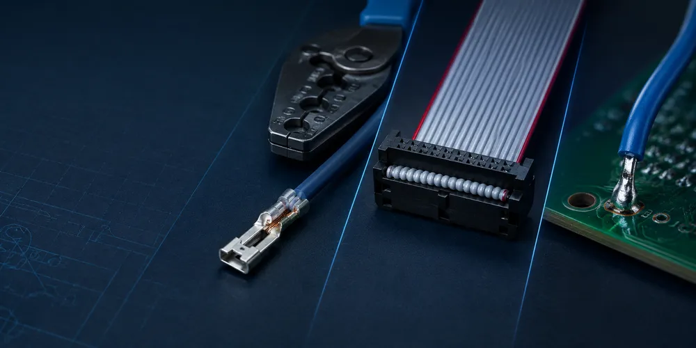
> Quality rule: A reliable termination is defined by the connector manufacturer’s approved terminal, wire, applicator and inspection criteria—not by a generic crimp height or a visual impression alone.
Quick Comparison
| Factor | Crimp | IDC | Solder |
|---|---|---|---|
| Tool required | Crimp tool ($50–500) | IDC press (or pliers) | Soldering iron |
| Skill required | Low (tool does work) | Very low | High (technique-dependent) |
| Speed per termination | 10–20 sec | 2–3 sec | 30–60 sec |
| Reworkability | Moderate (can de-pin) | ❌ Single-use | ✅ Re-solder possible |
| Long-term reliability | Highest (gas-tight crimp) | Medium | Variable (cold joints) |
| Wire prep | Strip (precision) | ❌ None (no stripping) | Strip + tin |
| Contact resistance | Lowest | Medium | Low |
| Vibration resistance | Excellent | Good | Poor (rigid joint) |
| Batch consistency | Very high (machine) | High | Low (human variable) |
| Best for | Production, reliability | Ribbon cable, mass wiring | Prototype, repair |
1. Crimp Termination: The Production Standard
Crimping uses a metal terminal that is mechanically deformed around the wire. A proper crimp creates a gas-tight connection — metal-to-metal contact with no air gap, preventing oxidation.
What Makes a Good Crimp
| Quality Factor | Good Crimp | Bad Crimp |
|---|---|---|
| Conductor crimp | Wire strands fully compressed, no gaps | Loose strands, air pockets |
| Insulation crimp | Grips insulation, provides strain relief | Insulation crushed or not gripped |
| Crimp height | Within spec (±0.05mm) | Too high (loose) or too low (broken strands) |
| Pull-out force | Meets the terminal manufacturer’s approved test requirement | Wire pulls out easily |
Crimp Quality Verification
| Test | Method | Pass Criteria |
|---|---|---|
| Crimp height | Micrometer on crimped section | Within datasheet spec |
| Pull test | Tension to failure | Wire breaks before crimp slips (or meets min force) |
| Visual | 10× magnification | No exposed conductor, no cracked strands, terminal not deformed |
A crimp is verified by crimp height measurement, not by feel. Even “feels tight” crimps can have hidden voids. See Crimp Tool & Quality Guide.
2. IDC Termination: Fastest, Single-Use
Real Product Examples
| Method | Brand and model | Correct use |
|---|---|---|
| Crimp | JST PH: PHR-2 + SPH-002T-P0.5S |
Use the PH-specific approved crimp process and matching header |
| Crimp | Molex Micro-Fit 3.0: 43045-0200 + 43025-0200 |
Select header, terminal and wire as one controlled system |
| IDC | 3M 89110-0101HA |
10-contact IDC socket for 0.050 in pitch ribbon cable; verify cable conductor construction and mating header |
The JST PH and 3M 891 Series documentation should be used as the acceptance baseline for those examples.
Insulation displacement contact (IDC) connectors slice through wire insulation to contact the conductor directly. No stripping required.
How It Works
“`
Ribbon cable laid over IDC → IDC press forces cable onto blades → blades slice insulation → blade contacts conductor → done
“`
Advantages
| Advantage | Detail |
|---|---|
| Speed | 2–3 seconds per termination (vs 10–20s for crimp) |
| No stripping | Eliminates wire prep step |
| Mass termination | Terminates 10–64 wires simultaneously |
| Low skill | Machine/plier does all the work |
Limitations
| Limitation | Detail |
|---|---|
| Single-use | Cannot be removed and re-terminated on the same spot |
| Wire spec strict | Only works with specified solid/stranded wire gauge |
| Higher resistance | Blade contact area smaller than crimp |
| Not for flexing | Blade connection can degrade with cable flexing |
3. Solder Termination: Prototype and Repair
Soldering connects wire directly to a connector contact or pad. It’s the most flexible but least consistent method.
When Solder Is Appropriate
| Scenario | Why Solder |
|---|---|
| Prototyping | No special tools needed |
| Repair | Re-solder a broken connection |
| Custom wiring | Odd wire sizes, no matching crimp terminal |
| Low volume | Not worth tooling for crimp |
When Solder Is Inappropriate
| Scenario | Why Not Solder |
|---|---|
| Production (high volume) | Inconsistent quality, slow, labor-intensive |
| Vibration environment | Solder joint is rigid — cracks under flex |
| High reliability | Cold joints are a common hidden defect |
| Small pitch connectors | Solder bridges and shorts |
The Cold Joint Problem
A cold solder joint looks fine but has a high-resistance, mechanically weak connection. It’s caused by insufficient heat, movement during cooling, or contamination. Cold joints are the #1 cause of solder-terminated wire failures — and they’re nearly impossible to detect by eye.
4. Choosing the Right Method
| Application | Recommended Method | Why |
|---|---|---|
| Production consumer electronics | Crimp | Reliability + speed + consistency |
| Ribbon cable internal wiring | IDC | Mass termination, no stripping |
| Battery pack assembly | Crimp (with proper tool) | High current, reliability |
| Prototype / breadboard | Solder or DuPont | No tooling cost |
| Automotive / aerospace | Crimp (machine-verified) | Industry requires crimped connections |
| Field repair | Solder | Practical in the field |
| High-vibration industrial | Crimp | Gas-tight, vibration-resistant |
5. GSConn Termination Offerings
| Series | Termination | Notes |
|---|---|---|
| W2B-PH / XH / SH | Crimp | Terminals + housings as system |
| W2B-IDC | IDC | 2.54mm ribbon cable, 10–64 circuit |
| W2B-SC | Solder (wire to board) | Direct solder cups for custom wiring |
| Pre-crimped leads | Crimp (factory) | GSConn pre-crimps wire leads — no tool needed by customer |
Pre-crimped leads are the best of both worlds: GSConn crimps the terminal onto the wire at the factory (machine-verified crimp quality), and the customer just inserts the lead into the housing. No crimp tool needed, full crimp reliability.
GSConn wire-to-board connectors support crimp, IDC, and solder termination. Pre-crimped leads available for all crimp series — factory-verified crimp quality eliminates the customer’s tooling cost and quality variability. Crimp height and pull-test data provided on request.
Related reading:
Related GSConn guides
Related reading on GSConn that complements wire-to-board-crimp-idc-solder: