
High-Density Board-to-Board Connectors: Fine-Pitch 0.4 mm and 0.5 mm Guide
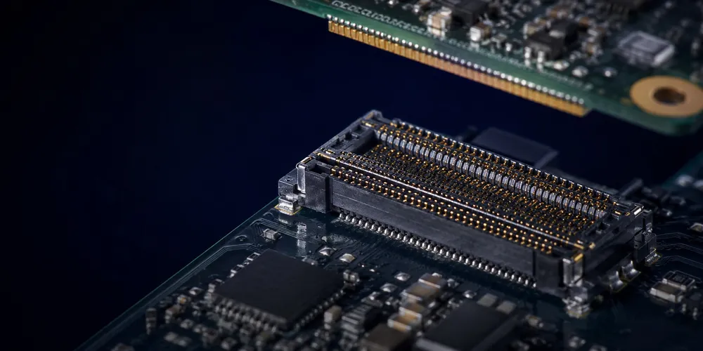
Fine-pitch board-to-board connectors are used when many signals must pass through a limited PCB area. Pitch is important, but it is only one part of density. Circuit count, row count, connector width, mated height, pad breakout, ground allocation, mechanical alignment, and assembly capability determine whether a fine-pitch connector is practical.
Key Takeaways
- Compare the full body, keep-out, and breakout area—not contact pitch alone.
- Select an exact plug/receptacle mating pair before freezing the footprint or stack height.
- Fine pitch narrows the SMT process window and increases the importance of alignment, board flatness, and supplier land patterns.
- High-speed suitability must be established from channel data and pin assignment, not inferred from density.
Quick Comparison
| Pitch Class | Main Advantage | Main Design Challenge | Typical Applications |
|---|---|---|---|
| 0.35–0.4 mm | Maximum density and very low profile | Fine land pattern, tight alignment | Mobile, wearables, compact modules |
| 0.5 mm | Strong density/assembly balance | Still requires controlled SMT process | Cameras, compact computing, industrial modules |
| 0.8 mm | More routing and mechanical margin | Larger footprint | Industrial, high-speed arrays, rugged systems |
| 1.0 mm+ | Easy handling and routing | Lower density | General equipment, serviceable electronics |
1. Pitch Is Not the Same as Connector Width
A common mistake is to estimate total connector width simply as contact count × pitch. Real connectors have two or more rows, end walls, hold-downs, guide features, and housing margins. Two 40-position connectors with the same pitch can therefore occupy different PCB areas.
When comparing density, use the manufacturer’s mechanical drawing and compare:
- total body length and width;
- circuit count and number of rows;
- recommended PCB keep-out;
- pad breakout area;
- required mating clearance;
- board-to-board height.
2. Real Fine-Pitch Product Families
Examples from established manufacturers show how broad the category is.
Hirose DF40
Hirose specifies the DF40 family at 0.4 mm pitch with multiple stacking heights from 1.5 to 4.0 mm. The series is positioned for high-density board-to-board and FPC-to-board connections and includes high-speed support in selected configurations.
Molex SlimStack
Molex SlimStack is a broad micro/fine-pitch board-to-board family with pitches starting around 0.35 mm and multiple mated-height and circuit-count options. Because SlimStack includes several sub-series, current, height, durability, and speed should be verified at the part-number level rather than applied to the entire family.
These examples illustrate why a generic statement such as “0.4 mm equals 0.3 A” is unreliable. Electrical capability is series-specific.
3. Fine-Pitch Assembly Challenges
Land pattern and stencil
Use the exact recommended land pattern from the selected part. At fine pitch, small changes in pad width, solder-mask registration, paste aperture, or connector coplanarity can materially affect yield.
Placement accuracy
Modern SMT equipment can place fine-pitch connectors accurately, but actual process capability depends on component geometry, fiducials, nozzle selection, board stability, and machine calibration. Do not set a universal placement tolerance from pitch alone.
Board flatness
Board bow and twist can become significant for long connectors. Wide high-pin-count arrays should be reviewed for PCB support and reflow warpage as well as terminal coplanarity.
4. Signal Integrity at High Density
Fine pitch brings signal conductors closer together, which can increase coupling. The correct solution is not simply “add a ground between every pair”; pin assignment depends on connector architecture and the interface.
For high-speed links:
- use the connector supplier’s validated pinout guidance when available;
- preserve return-path continuity;
- control differential impedance on the PCB;
- minimize breakout discontinuities;
- use S-parameters for channel simulation at higher data rates;
- review crosstalk with realistic neighboring-pin activity.
A larger-pitch connector with a well-engineered contact field may outperform a smaller-pitch connector for a high-speed channel, so density and bandwidth should be evaluated together.
5. Mechanical Reliability
Fine-pitch connectors often use short contacts and compact housings. Reliability depends on:
- self-alignment range;
- guide features;
- metal armor or hold-downs;
- effective mating length;
- connector protection during unmating;
- board stiffness;
- specified mating cycles.
Never assume that smaller pitch automatically means lower durability. Compare the actual qualification data for the selected series.
6. When 0.4 mm or 0.5 mm Pitch Makes Sense
Use fine pitch when one or more of the following dominate the design:
- connector footprint is a hard constraint;
- product thickness is tightly limited;
- high circuit count must fit a narrow board edge;
- mobile or wearable packaging requires very small interconnects;
- multiple interfaces must coexist in a compact module.
Use a larger pitch when:
- assembly margin is more important than absolute size;
- power contacts are a major part of the interface;
- operators will mate/unmate the boards frequently;
- contamination, vibration, or service conditions favor larger geometry.
7. Selection Workflow
- Define circuit count and signal types.
- Define maximum footprint and mated height.
- Determine current requirements and power/ground allocation.
- Identify required high-speed interfaces and simulation needs.
- Compare manufacturer drawings—not pitch labels alone.
- Verify assembly-house capability for the chosen land pattern.
- Prototype and inspect solder joints before production release.
GSCONN Selection Support
For a GSCONN high-density board-to-board project, provide the required pitch range, circuit count, stack height, signal rate, power allocation, operating temperature, mating cycles, and board-space limits. Use the released product drawing and datasheet as the authority for footprint and performance.
FAQ
Is 0.4 mm pitch always twice as dense as 0.8 mm?
Not at the connector level. Linear pitch is half, but housing width, rows, keep-out zones, and routing area determine the actual board-space saving.
Does fine pitch automatically reduce current capacity?
Often the contacts are smaller, but current rating is product-specific. Use the selected part’s datasheet and temperature-rise conditions.
Can a 0.4 mm connector carry PCIe or USB?
Some fine-pitch families support high-speed interfaces, but capability depends on the exact series, pin assignment, stack height, and PCB channel design.
Related reading:
- Low-Profile Board-to-Board Connector Guide
- SMT Board-to-Board Connector Guide
- PCB Board-to-Board Connector Design Guide
Technical References
- Hirose DF40 series overview
- Molex SlimStack connector portfolio
- GSCONN board-to-board connector portfolio
Related reading on GSConn
- Wire-to-Board vs Board-to-Board Connectors
- Industrial USB Connector Guide
- IP67 vs IP68 USB Connector
- Stacked USB Connector Guide
- Request a Quote
Engineering references
- Product drawing, datasheet, material declaration and qualification report for the selected connector series
- IPC land-pattern and acceptability guidance applicable to the PCB assembly class
- Project-specific vibration, shock, thermal and electrical requirements