
RF Coaxial Connector Guide: SMA, BNC, Type N, MCX, and More
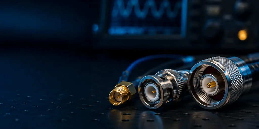
An RF connector is part of the transmission line. Even when two interfaces mate mechanically, the wrong impedance, launch geometry, cable, assembly method, or frequency grade can create reflections and loss. Select the connector and cable assembly together, using measured performance over the actual operating band.
Quick Reference
| Connector | Impedance | Frequency | Size | Common Use |
|---|---|---|---|---|
| BNC | 50/75Ω | up to 4 GHz | Medium | Test equipment, video, instrumentation |
| TNC | 50Ω | up to 11 GHz | Medium | Wireless, RF systems |
| SMA | 50Ω | up to 18 GHz | Small | Antennas, modules, test |
| SMB | 50Ω | up to 4 GHz | Small | PCB connections, compact |
| SMC | 50Ω | up to 10 GHz | Small | Military, telecom |
| N | 50Ω | up to 11 GHz | Large | Base stations, high power |
| MCX | 50Ω | up to 6 GHz | Micro | GPS, Wi-Fi, compact |
| MMCX | 50Ω | up to 6 GHz | Micro | GPS, small modules |
| U.FL / IPEX | 50Ω | up to 6 GHz | Ultra-micro | Wi-Fi, Bluetooth modules |
1. What Is a Coaxial Connector?
An RF coaxial connector maintains a controlled 50Ω (or 75Ω) impedance through the connection. It has:
– Center pin (signal)
– Dielectric insulator (maintains spacing = impedance)
– Outer shield (ground, also provides mechanical coupling)
The connector’s impedance must match the cable and equipment — any mismatch causes signal reflection, reducing the RF performance.
2. SMA: The Workhorse (Up to 18 GHz)
SMA (SubMiniature version A) is the most common RF connector for modules, antennas, and test equipment.
| Parameter | Specification |
|---|---|
| Impedance | 50Ω |
| Frequency | DC–18 GHz (some to 27 GHz) |
| Coupling | Threaded (1/4-36 UNF) |
| VSWR | <1.05 (typical) |
| Mating cycles | 500+ |
| Size | 4.1mm hex nut |
SMA Types
| Type | Use |
|---|---|
| SMA male (plug) | Cable end, threaded pin |
| SMA female (jack) | Equipment end, threaded socket |
| RP-SMA (reverse polarity) | Wi-Fi antennas — reversed gender |
RP-SMA is critical for Wi-Fi: FCC regulations require non-standard connectors on consumer Wi-Fi antennas. RP-SMA male has a socket in the center (reversed).
3. BNC: The Test Standard (Up to 4 GHz)
BNC (Bayonet Neill-Concelman) uses a bayonet coupling — push and twist to lock. Fast connect/disconnect, common in test equipment.
| Parameter | Specification |
|---|---|
| Impedance | 50Ω or 75Ω (version-dependent) |
| Frequency | DC–4 GHz |
| Coupling | Bayonet (push-twist) |
| Speed | Fastest connect of any RF connector |
75Ω BNC is used in video (composite, SDI). 50Ω BNC is used in RF test and instrumentation. Because the interfaces can appear similar, verify impedance before mating; mixing them introduces mismatch and may damage precision contacts.
4. N: The High-Power Standard (Up to 11 GHz)
N (Type N) connector handles higher power and provides better weather sealing than SMA.
| Parameter | Specification |
|---|---|
| Impedance | 50Ω |
| Frequency | DC–11 GHz |
| Coupling | Threaded (5/8-24 UNEF) |
| Power handling | Up to 1000W (at low frequency) |
| Sealing | Weatherproof versions available |
| Use | Base stations, antennas, high-power RF |
5. PCB-Mount Coaxial Connectors
| Connector | PCB Mount | Frequency | Use |
|---|---|---|---|
| SMA (edge mount) | Edge launch | 18 GHz | Module I/O |
| SMB (snap-on) | Through-hole/SMT | 4 GHz | Compact, quick connect |
| MCX | Through-hole/SMT | 6 GHz | GPS, cellular modules |
| MMCX | Through-hole/SMT | 6 GHz | Small modules, radio |
| U.FL/IPEX | SMT | 6 GHz | Wi-Fi, Bluetooth |
6. VSWR and Insertion Loss: What to Check
| Parameter | Definition | Good Value |
|---|---|---|
| VSWR | Voltage Standing Wave Ratio (reflection) | <1.2 |
| Insertion loss | Signal loss through connector | <0.1 dB |
| Return loss | How much signal reflects back | >20 dB |
A poorly matched connector reflects signal, which degrades the RF link. Always specify connectors matched to your cable and system impedance (50Ω vs 75Ω).
7. Selection Checklist
Specify impedance, operating-frequency range, maximum power, cable type, PCB or bulkhead launch, coupling method, environmental sealing, mating cycles, plating, VSWR/return-loss target, and insertion-loss budget. For PCB launches above several gigahertz, request the recommended land pattern and validate the complete transition with the actual board stack-up.
8. GSConn RF Coaxial Series
| Series | Type | Frequency | Features |
|---|---|---|---|
| RF-SMA | SMA male/female, RP-SMA | 18 GHz | Threaded, gold center pin |
| RF-BNC | BNC 50Ω/75Ω | 4 GHz | Bayonet, fast connect |
| RF-N | Type N | 11 GHz | High power, weatherproof |
| RF-MCX | MCX | 6 GHz | Compact PCB mount |
| RF-UFL | U.FL/IPEX | 6 GHz | Ultra-micro, Wi-Fi modules |
GSConn RF coaxial connectors cover SMA (including RP-SMA), BNC, N, MCX, and U.FL series in 50Ω and 75Ω. Gold-plated center pins, PTFE dielectric, and PCB-mount options. VSWR and insertion loss data available for all series.
Related reading:
– Circular Connector Selection Guide
– Heavy-Duty Rectangular Connector Guide
– M12 Connector Guide