
Pogo Pin Connector Design: Travel, Force and Current
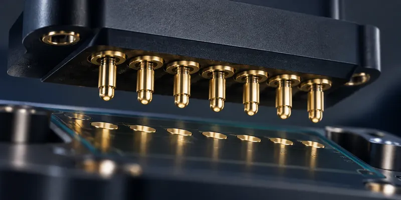
Pogo pins are spring-loaded contacts used in docking interfaces, charging contacts and test fixtures. Their ability to accommodate movement makes them useful, but reliable contact depends on controlled compression, alignment and surface condition.
Do not select a pogo pin from its diameter or advertised cycle count alone. The mechanical stack and electrical operating conditions determine whether it will work in the finished product.
Understand the contact mechanism
A typical spring-loaded contact includes a plunger, barrel and internal spring. The spring provides force as the plunger compresses; the conductive path depends on the internal contact design. Do not assume the spring alone carries the intended load current.
The mating target is part of the connection. Its finish, flatness, size and location affect contact quality as much as the pin itself.
Keep compression inside the recommended working range
Maximum stroke is a mechanical limit, not automatically the correct operating position. Obtain the manufacturer’s recommended working travel and evaluate both the minimum and maximum assembled gap.
For example, suppose a hypothetical pin is approved for 0.4–0.8 mm compression. A nominal 0.6 mm compression with ±0.1 mm total variation would span 0.5–0.7 mm. A ±0.3 mm variation would span 0.3–0.9 mm and exceed that specified range. These numbers illustrate the tolerance method, not a general pogo-pin recommendation.
Include PCB thickness, housing dimensions, target height, wear and assembly tolerance in the calculation. Provide mechanical stops where needed so the enclosure carries excessive closing loads rather than bottoming the plungers.
Balance force, alignment and retention
More spring force is not always better. It increases the force the latch, magnets or enclosure must resist and can increase target wear. For an array, evaluate total spring force at the relevant compression, plus any seal or friction loads.
Guide the mating parts so conventional axial plungers are not subjected to unintended side loading. Pad dimensions should accommodate the validated positional tolerance while preserving separation between adjacent contacts. Magnets can help retain or align an interface, but they do not replace mechanical tolerance analysis.
Select tips and mating finishes together
| Contact feature | Design question |
|---|---|
| Rounded tip | Is the target a suitable flat contact surface? |
| Flat tip | Are target alignment and surface condition controlled? |
| Crown or pointed test tip | Is the target intended to tolerate localized contact pressure? |
| Gold-finished target | Is the finish suitable for the wear and electrical requirements? |
| Exposed charging contacts | How are contamination, shorts and cleaning handled? |
There is no universal minimum gold thickness that guarantees a particular service life. Ask for the finish specification and durability evidence for the proposed pin-target combination.
Validate current and cycle life under realistic conditions
Current capability depends on resistance, internal construction, compression, mounting and heat dissipation. The target, PCB copper and return path also matter. Test temperature rise at the intended continuous and peak loads, with the real number of energized contacts.
Cycle-life claims require conditions: travel, speed, alignment, electrical load and the failure criterion. A result from a clean test fixture does not automatically represent an exposed consumer charging dock. Qualification must use the selected part’s data and a test setup representative of the intended application.
If several contacts share current, verify the sharing behavior. Small resistance differences can prevent equal current distribution. For high-speed signals, evaluate the interface electrically rather than assuming a short pin is automatically suitable.
FAQ
Are all pogo pins rated for one million cycles?
No. Ratings vary by construction and test conditions.
Can a magnetic dock supply the required contact force?
It may, but retention must exceed the relevant separating loads across the full tolerance range. Validate the complete dock.
Prepare a pogo-pin enquiry
Send GSConn the assembled gap range, target layout, current profile, cycle requirement and environmental exposure. Request a pin and target recommendation with working-travel and test data for the intended application.