
Server BMC USB Connector Requirements: A Platform Engineer’s Reference
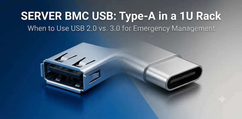
Every server has at least one USB port that the operating system never touches. It sits on the rear I/O panel, connected not to the host CPU complex but to the Baseboard Management Controller — and it is the last line of access when everything else has failed. If the OS crashes, if the BIOS is corrupted, if the network stack is misconfigured and the server becomes unreachable, that BMC USB port is how you get back in.
The connector on the other end of that port deserves more attention than it typically gets during platform design. This guide covers the technical requirements for server BMC USB connectors: why the specifications differ from front-panel or consumer ports, how they map to specific BMC chip generations, what internal USB headers actually connect to, and what to specify when designing or sourcing for this application.
The BMC Management Plane Architecture
A server’s USB connectivity splits between two distinct controllers:
| USB Domain | Controller | Typical Ports | Purpose |
|---|---|---|---|
| Host USB | CPU root complex (PCH/SoC) | Front panel, internal headers, some rear ports | OS-visible: storage, peripherals, user access |
| BMC USB | BMC SoC internal USB host | 1–2 rear panel ports | OS-invisible: KVM console, virtual media, firmware updates |
The BMC USB port is owned entirely by the BMC chip. The host CPU has no visibility into it. From the host OS perspective, those ports don’t exist — they don’t appear in lspci, dmesg, or Device Manager. This isolation is intentional: even if the OS is completely compromised, the BMC retains an independent access path.
This architecture has direct implications for connector selection. The BMC USB port:
- Is accessed almost exclusively by trained data center technicians, not end users
- Is used intermittently — perhaps dozens of times per year per server, not continuously
- Must work reliably after months or years without any mating cycles
- Must function without OS support, relying entirely on BMC firmware enumeration
- Must withstand the electrical environment of an active server chassis (high-frequency switching noise from VRMs, fan motors, PCIe slots)
BMC Chip Generations and USB Capability
The USB hardware available at the connector depends entirely on which BMC chip is on the motherboard.
ASPEED AST2500 (Legacy, widely deployed 2015–2020)
| Capability | Specification |
|---|---|
| USB host controller | Two USB 2.0 EHCI controllers |
| Host ports | 2× USB 2.0 (one typically routed to rear I/O, one to internal header) |
| USB device controller | One USB 2.0 device (virtual HID keyboard, virtual hub) |
| Maximum speed | 480 Mbps (USB High-Speed) |
| Virtual media | USB 2.0 mass storage class via virtual media over BMC network |
| Type-C support | None — USB 2.0 only |
AST2500 is the most widely deployed BMC in the installed base. Its USB 2.0-only architecture is why rear I/O panels on most production servers from 2015–2022 have USB Type-A connectors with no SuperSpeed (blue) markings.
ASPEED AST2600 (Current generation, 2020–present)
| Capability | Specification |
|---|---|
| USB host controller | Two USB 2.0 EHCI + two USB 3.0 xHCI controllers |
| Host ports | Up to 4× USB (mix of USB 2.0 and USB 3.0) |
| USB device controller | USB 2.0 device controller |
| Maximum speed | 5 Gbps (USB 3.2 Gen 1) on xHCI ports |
| Virtual media | USB 2.0 or USB 3.0 mass storage, significantly faster firmware transfer |
| Type-C support | Possible via external MUX; not standard in most board designs |
The AST2600 is the first BMC to offer USB 3.0 host ports in a shipping product. However, most platform designers still route USB 2.0 to the rear I/O BMC port, reserving the USB 3.0 capability for internal use (DOM boot media at higher speed) or leaving it unused. The connector at the rear I/O panel in an AST2600 platform may be physically USB Type-A but electrically USB 2.0 — the SuperSpeed signal traces are not routed to that port.
ASPEED AST2700 (Emerging, 2024–present)
| Capability | Specification |
|---|---|
| USB host controller | USB 3.2 Gen 2 (10 Gbps) xHCI |
| USB device controller | USB 3.2 device |
| Type-C support | Yes — AST2700 includes USB Type-C PHY |
| Virtual media performance | 10 Gbps bus allows mounting large images over high-bandwidth KVM |
AST2700 is the first BMC SoC to natively support USB Type-C. Platforms designed around AST2700 (expected in next-generation hyperscale ODM designs from 2025 onward) will begin appearing with USB Type-C BMC management ports. This changes connector selection requirements — Type-C receptacles require different footprints, higher pin counts, and different mechanical retention strategies than Type-A.
Non-ASPEED BMC Chips
| BMC Chip | USB Host | Notable Deployments |
|---|---|---|
| Pilot 4 (Emulex/QLOGIC) | USB 2.0 | Older HP/HPE iLO platforms |
| Pilot 5 (Nuvoton) | USB 2.0 | Nuvoton-based designs |
| Nuvoton NPCM750/NPCM845 | USB 2.0 (NPCM750) / USB 3.0 (NPCM845) | OpenBMC platforms, Meta/Google ODM servers |
| Renesas H3/H4 | USB 3.0 | Embedded BMC modules |
Why BMC USB Ports Are Almost Always USB 2.0
The persistence of USB 2.0 on rear-panel BMC ports is not negligence. Platform engineers choose USB 2.0 for these ports for specific, well-considered reasons:
Reason 1: Cable Length and Noise Margin
In a populated rack, the cable connecting a technician’s laptop to the rear of a 2U server runs through a rat’s nest of Ethernet bundles, power cables, and SFP+ patch cords. That electrical environment is hostile to high-speed differential signaling.
- USB 2.0 (FS/HS at 12/480 Mbps): tolerates up to 5 meters of cable with adequate signal margin
- USB 3.2 Gen 1 (SS at 5 Gbps): maximum cable length specification is 3 meters; actual performance in rack environments degrades earlier
- USB 3.2 Gen 2 (SS+ at 10 Gbps): 2-meter practical limit with quality cable
The typical data center KVM session — keyboard input, mouse movement, basic console output — runs at less than 1 Mbps of actual data. USB 2.0 is not a bottleneck here.
Reason 2: BMC Firmware Complexity
USB 3.0 requires more complex enumeration, power management, and link training sequences in the BMC firmware. USB 2.0 enumeration is simpler, faster to implement, and has a 25-year deployment history with no hidden edge cases. In BMC firmware — where bugs mean servers become unmanageable — conservative protocol choices reduce risk.
Reason 3: Connector Reliability
A USB 2.0 Type-A receptacle has 4 contacts. A USB 3.0 Type-A adds 5 SuperSpeed pins, thinner and closer together, with tighter tolerances. In connector reliability terms:
| Parameter | USB 2.0 Type-A | USB 3.0 Type-A |
|---|---|---|
| Contact count | 4 | 9 |
| Contact pitch (SS) | N/A | 0.9 mm |
| Mating force (typ.) | 5–30N | 10–35N |
| Typical rated cycles | 1,500–5,000 | 1,500–3,500 |
| Contact contamination risk | Low | Higher (more contacts) |
For a port used tens of times per year at most, the additional contacts of USB 3.0 add failure modes without adding useful bandwidth.
Internal USB Connectors: DOM Headers and Boot Media
The most overlooked USB connector on a server is internal. The 9-pin internal USB 2.0 header (or the dual-row 19-pin USB 3.0 header) on the motherboard connects to USB Disk-on-Module (DOM) devices used for hypervisor boot.
Internal USB 2.0 Header (9-Pin)
Pin 1: +5V         Pin 2: D- (Port 1)    Pin 3: D+ (Port 1)
Pin 4: GND         Pin 5: D- (Port 2)    Pin 6: D+ (Port 2)
Pin 7: GND         Pin 8: (Key/NC)       Pin 9: NC
This header carries two USB 2.0 ports on a single 9-pin connector. In most server deployments, only one port is populated — typically Port 1 — with a USB DOM device or a USB Type-A extension pigtail for removable media.
| USB DOM Use Case | Capacity Range | Typical Speed Requirement | USB Generation |
|---|---|---|---|
| VMware ESXi boot | 4–32 GB | Writes at install time only; boot reads at ~3 MB/s | USB 2.0 adequate |
| Proxmox VE boot | 8–64 GB | Similar write profile | USB 2.0 adequate |
| Windows Server DOM | 32–128 GB | Occasional update writes | USB 2.0 adequate for most |
| Logging / crash dump | 32–256 GB | Can saturate USB 2.0 on continuous writes | USB 3.0 preferred |
Internal USB 3.0 Header (19-Pin)
The 19-pin internal USB 3.0 header (also called the 20-pin header with key pin) provides two USB 3.2 Gen 1 ports. On platforms with AST2600/AST2700 BMCs that support USB 3.0, the BMC may route its USB 3.0 host port to this header instead of the rear I/O panel — allowing faster virtual media streaming over a USB 3.0 DOM device without exposing USB 3.0 externally.
The 19-pin header connector is mechanically fragile compared to the 9-pin — the key pin and close pitch create alignment sensitivity during assembly. For automated manufacturing environments, a locking variant with positive retention is strongly preferred.
DOM Connector Selection Criteria
| Parameter | Requirement | Rationale |
|---|---|---|
| Retention force | > 10N extraction per connector spec | Vibration in 2U/4U chassis from multiple fans |
| Operating temperature | 0°C to +70°C minimum | Server chassis ambient; some edge deployments require −20°C |
| Contact plating | Gold over nickel, min 15µ” gold | DOM is inserted once at assembly, but needs corrosion resistance over 5-year service life |
| ESD protection | Per USB-IF specification | Static from technician handling during installation |
| Locking mechanism | Clip or screw retention | Prevents accidental dislodging during chassis vibration |
Rear Panel BMC USB Connector: Mechanical Requirements
The rear I/O panel USB connector on a server sees a very specific use pattern: months of no mating activity, followed by use by a stressed data center technician who may be working at the back of a rack in low light with limited reach, inserting a cable from an unfamiliar angle.
This use pattern drives specific mechanical requirements that differ from front-panel consumer USB connectors:
Insertion Blindness Resistance
Technicians often insert rear-panel USB cables without direct line of sight. The connector must guide the plug into the correct orientation without requiring visual confirmation. This is why:
- The USB Type-A keying (asymmetric housing) must be maintained with tight tolerance — a connector housing that has deformed under thermal cycling will allow rotated insertions that damage contacts
- Chamfer on the port entry should be 0.3–0.5 mm minimum to provide tactile guidance
- Some server designs add a tactile bump or raised ring around the USB port on the rear I/O panel bezel for tactile location without sight
Retention Under Cable Weight
In a populated rack, the USB cable connected to the rear BMC port may have a management arm adapter or heavier cable assembly. The connector must retain the mated plug against the cable’s own weight plus gentle side-loading without relying on the plug’s retention clip alone:
| Retention Mechanism | Extraction Force | Application |
|---|---|---|
| Standard USB-A friction | 5–15N | Consumer; not recommended for rack environments |
| Locking USB-A (screw-lock) | > 30N | Data center and industrial deployments |
| Panel-mount retention bracket | Structural (mount to panel) | High-density servers with limited bezel depth |
Shielding and Ground Continuity
The server chassis ground and the connector shield must have continuous low-impedance connection. A connector with poor shell-to-chassis ground continuity becomes an EMI radiator in the high-noise environment of an active server:
- Shell contact to PCB ground via 4× SMT pads minimum for chassis-mount designs
- Shield connection should be established before signal contacts on insertion (shell longer than contact depth)
- In stacked connector designs (USB+RJ45 combo), the shared shell provides common-mode noise rejection across both interfaces
BMC USB in High-Availability Configurations
Some high-availability server platforms route the BMC USB to a different connector arrangement:
Shared BMC/Host USB
In blade and modular chassis designs, a single USB port may be shared between the BMC and the host CPU through a USB MUX (multiplexer). The MUX state is controlled by the BMC:
- BMC active (no OS boot): BMC owns the USB port for KVM console and virtual media
- OS running (normal operation): USB port switched to host for administrator access
This requires a connector that supports the full mating cycle requirements of both uses combined — typically specified at 5,000 mating cycles minimum.
Redundant Management Ports
Enterprise platforms (Dell PowerEdge, HPE ProLiant, Lenovo ThinkSystem) typically provide two BMC management paths: the dedicated BMC USB port and the iDRAC/iLO/XCC Ethernet management port. The USB port handles:
- KVM console when the management LAN is unreachable
- Virtual media for OS reinstallation when PXE boot is unavailable
- BIOS recovery when firmware corruption prevents normal boot
For these use cases, the USB connector is the connector of last resort — it must work when nothing else does. This demands a higher reliability specification than a port used daily, because it may be tested only in emergencies.
USB Type-C Transition on Servers: What to Expect
The transition from USB Type-A to USB Type-C on server rear panels is underway but slow. The connector change has implications beyond plug geometry:
| Transition Factor | USB Type-A (Current) | USB Type-C (Emerging) |
|---|---|---|
| BMC chip support | AST2500/2600 — USB 2.0 | AST2700 — USB 3.2/Type-C |
| Reversibility benefit | Limited in rear-panel use | Reduces misalignment damage in low-visibility access |
| Cable ecosystem | Mature; every rack has USB-A cables | Requires USB-C cables in rack kit |
| Power delivery | 5V 0.9A max (USB 2.0) | Must disable PD; data-only mode |
| Mechanical robustness | Type-A insertion force: 5–30N; robust shell | Type-C: 5–20N; 24-contact shell more fragile |
For platform engineers designing around AST2700: Type-C on the BMC port is technically viable but requires explicit PD negotiation disable in BMC firmware and attention to the 24-contact shell’s lower tolerance for abuse.
Stacked and Combo Connectors for Server Management Ports
The 1U server rear panel is cramped. A 1U chassis has approximately 44mm of vertical space, shared between power connectors, data-plane SFPs, fan exhaust, and the management plane ports. In this space budget, a USB + RJ45 combo connector (stacked jack) saves significant panel real estate:
| Configuration | Panel Height | Width | Ports |
|---|---|---|---|
| Discrete USB-A + discrete RJ45 | 2× standard heights | ~30mm combined | 1+1 |
| Stacked USB-A over RJ45 | 1× combined height | ~16mm | 1+1 |
| Dual stacked USB-A + stacked RJ45 | 1× combined height | ~32mm | 2+1 |
| USB-A + USB-A stacked | 1× combined height | ~15mm | 2 |
Stacked connectors are standard in 1U server designs from Dell, HPE, Supermicro, and whitebox ODMs. The stacked configuration uses a common shell that grounds both USB and RJ45 shields — improving EMI performance compared to two separate connectors with independently grounded shells.
Key stacking considerations for server management ports:
– USB must be positioned for easier single-port access (bottom position allows the plug to rest without support)
– RJ45 magnetics must have adequate isolation from USB signal traces in the PCB layout
– Combined shield continuity to chassis ground requires careful footprint design
– Depth from panel face must accommodate both USB and RJ45 plug simultaneous mating
GSConn manufactures stacked USB+RJ45 combo connectors for 1U server applications. For configurations combining USB 2.0 management port with 1GbE IPMI management LAN, contact GSConn for panel-mount and SMT stacking options.
Connector Selection Checklist for Server BMC USB Ports
When specifying USB connectors for server BMC management plane use:
Mechanical
– [ ] Connector type matches BMC chip USB generation (USB 2.0 Type-A for AST2500/2600; consider Type-C for AST2700)
– [ ] Mating cycle rating ≥ 1,500 cycles (standard); ≥ 5,000 for shared BMC/host ports
– [ ] Shell material: SPCC steel minimum; SUS304 preferred for harsh environments
– [ ] Retention option specified if rack vibration or cable weight is a factor
– [ ] Chamfer and entry geometry designed for blind insertion
Electrical
– [ ] Contact plating: gold over nickel, minimum 15µ” gold for reliability
– [ ] ESD protection: USB-IF compliant at connector level
– [ ] Shield grounding: 4-point PCB attachment for shell-to-GND continuity
– [ ] For stacked designs: USB and RJ45 signal isolation ≥ 40 dB
Environmental
– [ ] Operating temperature: 0°C to +70°C minimum; −40°C to +85°C for edge/industrial deployments
– [ ] Humidity: 5–95% RH non-condensing
– [ ] IP rating: IP20 for standard server rooms; IP54–IP67 for edge/outdoor data centers
Internal DOM Headers
– [ ] 9-pin (USB 2.0) or 19-pin (USB 3.0) header matches DOM device connector
– [ ] Retention force matches vibration profile of chassis
– [ ] Header orientation provides clearance for cable routing around adjacent heatsinks/VRM
Summary: BMC USB Connector Principles
The BMC USB port on a data center server is a low-usage, high-criticality interface. The connector specifications that matter most are not data rate or power delivery — they are:
- Mechanical reliability over years of idle deployment — corrosion resistance, contact plating, housing material stability
- Reliable blind insertion — geometry and chamfering for technician access in constrained spaces
- EMI performance in active server environment — shell grounding, shielding continuity
- Compatibility with BMC chip generation — USB 2.0 for AST2500/2600; USB 3.0/Type-C for AST2700 and future platforms
The connector choice is invisible during normal server operation. It becomes critical exactly when the server needs it most: during an outage, a firmware recovery, a console session over a failed network — the moments when “the USB port works” is the difference between a 5-minute remote fix and a $150/hour truck roll.
Related guides on this site: Data Center Server Connectors: Complete Guide | Stacked USB+RJ45 Combo Jack for Server I/O | USB Connector Signal Integrity and Performance Specs
GSConn supplies USB Type-A, USB Type-C, RJ45, and stacked USB+RJ45 combo jack connectors for server BMC management ports and rear I/O panels. Our server-grade portfolio includes internal USB 2.0 Type-A headers (9-pin) for DOM and HSM modules, rear-panel USB Type-A and Type-C receptacles rated for AST2500/2600/2700 BMC SoCs, and stacked USB+RJ45 configurations that reduce 1U/2U server panel footprint by up to 40%. Industrial-temperature variants (-40 to +105 °C) are available for edge and outdoor server deployments. Custom pinout, plating thickness (15–50 µ”), and PCB footprint support are provided for OEM server designs.
Related Reading: Data Center Server Connectors: Complete Guide · RJ45+USB Combo Jack for Server I/O · USB Connector Signal Integrity Specs · Panel Mount USB Connector Selection Guide · Stacked USB Connector Design Guide