
Stacked USB Connector Pros and Cons: Engineering Tradeoffs Before Layout
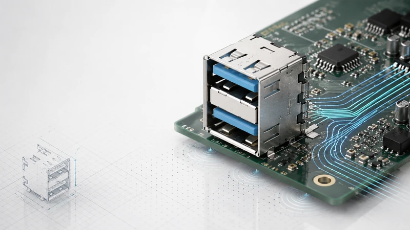
A stacked USB connector is an elegant way to put two ports into a narrow panel space. It is also a part that can create signal-integrity, mechanical, and thermal tradeoffs if it is selected only for footprint savings.
The practical decision is not “stacked connectors are good” or “stacked connectors are bad.” They are good when width and panel space are the limiting factors. They are less attractive when high-speed margin, frequent cable insertion, or high current is the dominant requirement.
Summary table
| Factor | Stacked connector advantage | Stacked connector tradeoff |
|---|---|---|
| PCB width | Two ports in about the width of one connector body | Taller above the PCB. |
| Panel design | One cutout and one sealing area | Cable access can be tight. |
| USB 2.0 signal margin | Usually very comfortable | Still needs normal ESD and routing discipline. |
| USB 3.x signal margin | Works when shielded and well laid out | Less margin than well-spaced ports. |
| Mechanical stress | Compact and clean front panel | Upper port creates more PCB leverage. |
| Cost | Can save panel/PCB area cost | Connector itself is usually more expensive. |
| Service | Clear top/bottom port roles | Top cable can block bottom access in small recesses. |
1. Advantages
1.1 Width savings
This is the main reason to use a stacked connector. In a compact industrial controller, router, gateway, or 1U server, the I/O edge can be more constrained than the total PCB area. A stacked connector keeps two USB ports in a narrow column and leaves the remaining panel width for Ethernet, power, antenna, HDMI, or service labeling.
For USB 2.0 designs, the space saving often comes with little electrical downside. That is why stacked USB-A connectors are common on embedded computers and equipment where the USB ports are primarily service or management interfaces.
1.2 Simpler panel sealing
One opening is easier to seal than two. If the product needs splash resistance, dust protection, or a gasketed panel, a stacked connector reduces the number of leak paths. It can also simplify EMI gasket placement because the two ports share one shielded connector body.
The final IP performance still depends on the whole panel assembly: cutout tolerance, gasket compression, screws, connector flange, cap, and mating cable.
1.3 Cleaner service layout
A stacked pair lets the product define a simple service convention: upper port for service, lower port for storage; or upper for data, lower for keyboard/mouse. That clarity reduces field mistakes, especially on gateways and medical carts.
2. Disadvantages
2.1 Less signal-integrity margin at high speed
At USB 3.x speeds, the connector body is part of the channel. The upper port generally has a longer internal path, and the two ports are closer together than side-by-side connectors. A good shielded stacked connector can work well at 5 Gbps, but it leaves less margin than two separated connectors with clean routing.
For 10 Gbps and above, treat the stacked option as a part-specific engineering decision. Ask for the connector model, layout guidance, and SI data early. Do not assume a USB 3.0 stacked Type-A connector is suitable for USB4; USB4 is a Type-C ecosystem.
2.2 More mechanical leverage on the PCB
When a user inserts a cable into the upper port, the force is applied farther above the PCB. That creates a bending moment at the solder joints and shell stakes. In a stationary desktop product, this may be acceptable. In a product with frequent service, vibration, or long cables, the connector should be reinforced.
Practical fixes include through-hole shell stakes, a local chassis bracket, a panel-mount connector, or a nearby PCB mounting screw.
2.3 More height
Stacked connectors save width by using height. Low-profile enclosures, stacked boards, or products with a shallow front bezel may not have the clearance. Always check the cable overmold in the 3D model, not only the empty connector.
2.4 Possible thermal imbalance
For ordinary USB service and data ports, connector heat is usually not the limiting issue. For sustained high current, especially Type-C power applications, stacked vertical geometry can make the upper port less thermally coupled to the PCB. If the product is power-heavy, review the thermal design instead of choosing stacked by default.
2.5 Higher component cost and fewer alternates
A stacked connector is a more complex molded part. It can cost more and may have fewer second sources than two ordinary single connectors. That does not make it more expensive at the product level; panel and PCB savings can offset the component price. But purchasing should check lead time and cross-reference options before the footprint is frozen.
3. When stacked is a strong choice
Use stacked USB when most of the following are true:
- I/O panel width is tight.
- The product needs two external ports in the same service area.
- USB 2.0 is enough, or USB 3.x margin has been reviewed.
- One sealed cutout is better than two openings.
- The connector can be supported mechanically.
- The cable overmold and service access are verified in the enclosure.
Typical good fits include industrial gateways, servers with management ports, compact embedded PCs, smart-building controllers, medical carts, and outdoor service panels.
4. When side-by-side is safer
Use two separate connectors when:
- USB 3.x or 10 Gbps performance is the dominant requirement;
- the enclosure has plenty of width but little height;
- users insert and remove cables many times per day;
- high-current charging is part of the product requirement;
- easy rework, second sourcing, or low component cost is more important than panel width.
Side-by-side ports are mechanically simpler and usually give cleaner high-speed routing. They are not automatically better; they simply spend width to gain margin.
5. Right-angle stacked: the compromise option
Right-angle stacked connectors can provide some footprint benefits while changing the mechanical and signal-routing geometry. They may reduce some vertical-stacking drawbacks, but availability is more limited and the footprint is more vendor-specific. Use them when the enclosure benefits are clear and the supplier can provide drawing, samples, and layout support early enough.
6. Datasheet red flags
A stacked connector datasheet should give more than body dimensions. Be careful if the drawing omits shell grounding details, recommended PCB keep-outs, plating information, mating-cycle rating, or the exact panel cutout. For USB 3.x, a supplier should also be able to explain whether the part is shielded and whether SI guidance or test data is available.
Another warning sign is a broad claim such as “USB4 ready” without a connector type, channel test condition, or compliance evidence. Treat high-speed claims as part-number-specific until proven otherwise.
7. GSConn selection notes
For GSConn stacked USB projects, start with the constraint that is actually limiting the design: panel width, enclosure sealing, USB speed, vibration, current, or temperature. Then select the connector style. Good specification language includes mounting type, USB generation, shielding, temperature range, sealing, plating/mating-cycle expectation, and required documentation.
For USB 3.x, ask for SI guidance and a recommended PCB footprint. For high-vibration products, ask for bracket or panel-mount options. For regulated or long-life products, confirm the change-control and material documentation process.
FAQ
Are stacked connectors bad for signal integrity?
No. They are simply less forgiving at high speed. USB 2.0 is usually comfortable; USB 3.x needs a shielded connector and disciplined layout.
Does the upper port wear faster?
Not because it is upper. Wear depends on contact design, plating, user handling, contamination, and mating cycles. The mechanical stress on the PCB is the larger stacked-specific concern.
Can stacked connectors be waterproof?
Yes, with the right panel-mount and gasket design. The finished product should be tested as an assembly.
Can I mix USB 2.0 and USB 3.x in one stacked housing?
Yes, if the supplier offers that configuration. Confirm pinout, shielding, and port labeling before layout.