
Vibration Resistant Dual USB Connector: PCB Layout and Mechanical Retention
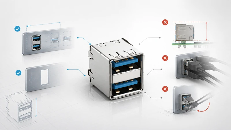
USB was not created as a high-vibration interface. It works well in stationary electronics, but the same connector can become unreliable on a DIN-rail controller, a vehicle gateway, a rail cabinet, or a machine tool if the cable and PCB are allowed to move.
A vibration-resistant dual USB design is not just a “rugged connector.” It is a system made of the connector, mounting method, cable retention, PCB support, enclosure, and test plan.
Practical selection matrix
| Environment | Main risk | Recommended approach |
|---|---|---|
| Office or rack equipment | Accidental pull | Standard stacked USB is usually enough. |
| Factory floor / DIN rail | Cable movement, occasional shock | Through-hole stacked USB; add strain relief. |
| Mobile cart / AGV | Repeated vibration | Through-hole plus bracket or locking cable. |
| Railway / roadside cabinet | Random vibration + temperature cycling | Panel-mount or bracketed connector; locking cable. |
| Heavy equipment / marine | Vibration, humidity, corrosion | Sealed panel-mount connector and controlled cable harness. |
1. Where vibration actually causes failures
Vibration problems rarely start as a connector falling out on day one. More often, the product passes functional test and then develops intermittent field failures.
The common mechanisms are:
- Contact micro-motion. Small relative movement at the contact interface increases contact resistance and can cause short dropouts.
- Fretting wear. Repeated micro-motion can wear plating at the contact point and expose base metal.
- Solder joint fatigue. A stacked connector has height; the upper port creates leverage on the PCB during vibration and cable insertion.
- Cable whip. A heavy or unsupported cable becomes a moving mass attached to the connector.
- Housing damage. Plastic features can crack if the connector resonates with the vibration profile.
A locking cable helps with pullout, but it does not automatically solve cable whip or solder fatigue. The cable must still be clamped or strain-relieved.
2. Standards and test references
Different industries use different vibration profiles. Do not pick a connector only by a generic “rugged” claim; match the product to the environment.
| Standard / reference | Typical use | What to clarify |
|---|---|---|
| IEC 60068-2-6 | Sinusoidal vibration | Frequency range, acceleration, sweep rate, axes. |
| IEC 60068-2-64 | Random vibration | PSD profile, duration, mounting condition. |
| IEC 61373 | Railway equipment | Category and location in the rail system. |
| ISO 16750-3 | Road vehicles | Body/chassis location and temperature combination. |
| MIL-STD-202 Method 204 | Component-level sinusoidal vibration | Useful for parts, not a substitute for product-level testing. |
The important question is whether the connector is tested alone or as installed in the product. A connector mounted on a thick test coupon may perform differently from the same connector on a narrow PCB tab.
3. Mechanical retention options
Standard friction retention
Suitable for stationary equipment. It is low-cost and uses ordinary cables, but it is not the right choice when cable movement is continuous or unplugging causes operational risk.
Screw-lock retention
The most common industrial solution. It prevents accidental unplugging and reduces motion at the interface when used with the matching cable. Leave access for the screw head and use through-hole or panel mounting so the retention force is not carried by SMT pads.
Latch retention
Useful for equipment that needs frequent service. Latches are easier to release than screws, but they depend on the correct cable. Validate the cable and receptacle as a pair.
Panel-mount retention
Best when vibration and cable pull are both present. The connector is mechanically tied to the enclosure, while the PCB is connected separately. This is usually the safest architecture for vehicles, rail, outdoor cabinets, and washdown equipment.
4. Through-hole vs SMT under vibration
| Mounting style | Vibration suitability | Notes |
|---|---|---|
| SMT pads only | Low | Good for compact consumer products; poor for field-accessible locking ports. |
| SMT with mechanical posts | Moderate | Acceptable when cable loads are controlled. |
| Through-hole shell stakes | Good | Practical default for industrial stacked USB. |
| Through-hole + chassis bracket | Very good | Transfers bending moment away from PCB. |
| Panel mount | Best | Enclosure carries the load. |
For stacked connectors, pay special attention to the upper port. Insertion force at the upper port creates a larger moment arm than a low-profile single USB connector. Reinforcement is cheap compared with field returns.
5. PCB layout and enclosure design
Good vibration performance starts in the mechanical layout.
- Keep the connector close to a PCB mounting point.
- Avoid long, narrow PCB tabs carrying the connector.
- Use shell stakes or mechanical posts where available.
- Add a bracket when the upper port is frequently used.
- Clamp the cable within a short distance of the connector if the product vibrates.
- Do not place heavy components beside the connector on an unsupported board edge.
For through-hole parts, specify solder fillet inspection criteria. For SMT or hybrid parts, check the solder joint shape after reflow and after vibration testing. If underfill or adhesive is used, make sure it does not trap flux residue or prevent rework.
6. Fretting corrosion: the quiet failure mode
Fretting is one reason a product can pass a continuity test and still fail later. Tiny movement at the contact point repeatedly breaks the surface film and can increase resistance. The symptoms are intermittent: the device reconnects, storage remounts, or the OS reports USB resets.
Mitigation is practical rather than exotic:
- prevent cable movement with strain relief;
- increase mechanical support at the connector;
- use a connector with appropriate plating and normal force;
- avoid using the port as a permanent hanging point for a heavy dongle;
- test with the real cable attached, not only with a bare connector.
7. How to test the finished design
A useful vibration validation plan includes the assembled PCB, enclosure, mating cable, and any strain relief.
Recommended checks:
- Run the chosen sinusoidal or random vibration profile in all required axes.
- Monitor continuity during the test; post-test inspection alone can miss dropouts.
- Log USB resets at the operating-system level during vibration.
- Measure contact resistance before and after the test.
- Inspect solder joints, shell stakes, panel screws, and cable clamps.
A realistic acceptance criterion is “no functional disconnects during the test,” not merely “no visible damage after the test.”
8. GSConn selection notes
For vibration-resistant dual USB projects, GSConn should be specified by mounting style first: through-hole stacked, bracket-supported stacked, or panel-mount stacked. Then add the required retention style, temperature range, plating, and sealing requirement. If the port will remain connected during operation, request the mating cable recommendation at the same time as the connector drawing.
For high-vibration programs, ask for vibration and shock test data for the selected configuration, not for a different member of the connector family.
Design review checklist
- [ ] Is the vibration profile defined by frequency, acceleration/PSD, duration, and axis?
- [ ] Is the test performed with the actual cable and enclosure?
- [ ] Is the connector supported by through-hole stakes, a bracket, or the panel?
- [ ] Is there cable strain relief close to the port?
- [ ] Are USB resets monitored during vibration?
- [ ] Is the connector also rated for the product temperature and humidity range?