
How to Test USB Connector — Continuity, Resistance & Signal Checks
Quick Test Reference
| What to Check | Tool | Expected Reading | What It Means If Off |
|---|---|---|---|
| Continuity (pin to pin) | Multimeter (continuity mode) | Beep / <1Ω | Open or high resistance |
| Contact resistance | Milliohm meter (4-wire) | <30mΩ per contact | Worn plating or contaminated contact |
| Shorts between pins | Multimeter (resistance) | >1MΩ (open) | Short circuit, bent pin, solder bridge |
| VBUS voltage | Multimeter (DC volts) | 4.75–5.25V | Power supply issue, not the connector |
| Data signal integrity | Oscilloscope, USB protocol analyzer | Clean eye diagram | Connector or PCB trace degradation |
| Physical / visual | Eyes, magnification | No damage, no bent pins, gold intact | Physical damage, replace connector |
1. Visual Inspection (Do This First)
Before any electrical test, look at the connector:
| Check | What to Look For |
|---|---|
| Pins | Bent, missing, or pushed back into housing |
| Gold plating | Shiny gold? Worn to gray nickel = worn out |
| Plastic housing | Cracks, discoloration (overheating), deformation |
| Solder joints | Shiny fillets on all pads, no cracks, no cold joints |
| Debris | Dust, lint, metal fragments in connector |
| Alignment | Connector perpendicular to PCB, not tilted |
Many USB connector problems are visible without tools. Debris in the connector is the most common cause of “USB not working.”
2. Continuity Test (Multimeter)
Check that each pin on the plug side connects to the corresponding pad on the PCB.
USB 2.0 Type-A Pinout
| Pin # | Signal | Color (standard cable) |
|---|---|---|
| 1 | VBUS (+5V) | Red |
| 2 | D- | White |
| 3 | D+ | Green |
| 4 | GND | Black |
Procedure
- Set multimeter to continuity mode (diode symbol with sound waves)
- Clip one probe to the USB pin (inside receptacle) or to the cable end (if testing cable)
- Touch other probe to the corresponding PCB pad or solder joint
- Multimeter should beep with <1Ω reading
- Repeat for all 4 pins
- Also test shield to GND — should be connected (0Ω) or have a small ferrite bead/RC network (not completely open)
What Results Mean
| Reading | Diagnosis |
|---|---|
| Beep, <1Ω | Normal |
| No beep | Open circuit — broken trace, bad solder joint, or bent pin not making contact |
| Beep but >5Ω | High resistance — contaminated contact, worn plating, cold solder joint |
| Beep between adjacent pins | Short circuit — solder bridge or bent pin touching neighbor |
3. Contact Resistance Measurement (Milliohm Meter / 4-Wire)
Standard multimeter cannot measure milliohm-level resistance accurately (lead resistance is 0.1–0.5Ω). Use a 4-wire (Kelvin) milliohm meter:
- Force current through the contact pair (plug pin → receptacle pin) using two wires
- Measure voltage drop across the contact using two separate sense wires
- Resistance = V / I (Ohm’s law)
Expected values:
| Connector Type | New | After Rated Cycles | Fail Threshold |
|---|---|---|---|
| USB 2.0 Type-A | <30mΩ | <40mΩ | >50mΩ |
| USB 3.0 Type-A | <30mΩ | <40mΩ | >50mΩ |
| USB Type-C | <40mΩ | <50mΩ | >60mΩ |
Contact resistance above 50mΩ causes USB enumeration failures: the host detects VBUS but D+/D- signaling is degraded by excessive series resistance.
4. Short Circuit Test
- Set multimeter to resistance mode (Ω), auto-range
- Probe adjacent pins: 1–2, 2–3, 3–4
- Resistance typically should be >1MΩ (display shows “OL” or infinity)
- If resistance is <10kΩ, there’s a short (solder bridge, bent pin, damaged insulator)
- Also test each pin to shield (GND): pin 1 (VBUS) to GND typically should be >1MΩ
5. VBUS Voltage Check (Powered Device)
With device powered and USB cable connected to host:
- Set multimeter to DC voltage, 20V range
- Probe VBUS (pin 1) to GND (pin 4) at the receptacle
- Expected: 4.75–5.25V (USB 2.0 spec), 4.45–5.25V (USB 3.0 spec, more tolerant due to IR drop)
- If voltage is 0V, check:
- Host USB port is powered and enabled
- Cable continuity (VBUS wire broken?)
- Fuse or PTC on device PCB (blown?)
6. Cable Testing
Bad cables cause more “connector” problems than connectors do. Test each wire independently:
| USB 2.0 Cable Wire | Color | Test |
|---|---|---|
| VBUS | Red | Continuity end-to-end |
| D- | White | Continuity |
| D+ | Green | Continuity |
| GND | Black | Continuity |
| Shield | Bare / drain | Continuity shield-to-shield |
Also check:
– Short between any two wires: Should be open (infinite resistance)
– Short to shield: VBUS typically should not short to shield
– Cable flex test: Continuity typically should remain stable while bending cable at connector strain relief
7. Advanced: Signal Integrity (Oscilloscope)
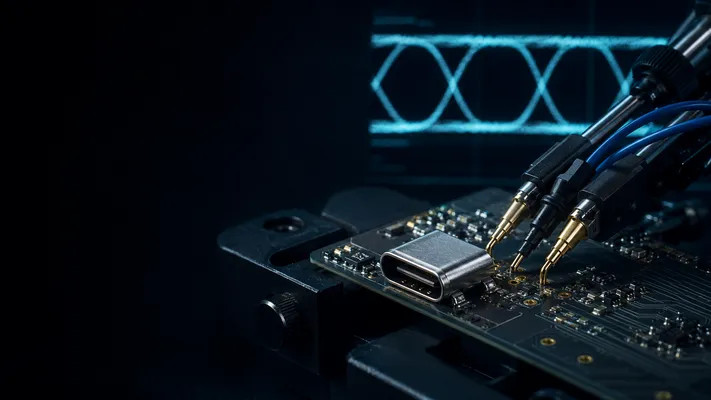
For USB 3.0+, signal integrity matters. An oscilloscope with >2.5 GHz bandwidth can capture USB 3.0 eye diagrams.
Quick Check (USB 2.0)
- Probe D+ and D- at the connector (differential probe recommended)
- Trigger on USB SOF (Start of Frame) packet
- Check eye opening: wide, clean transitions, no excessive jitter
Pass/fail: If USB enumerates and transfers data without errors, signal integrity is adequate. An oscilloscope test is only needed when you have intermittent enumeration failures or CRC errors in the USB protocol analyzer.
Test Limits Need a Product Specification
Continuity testing confirms that pins are connected, but it does not prove USB 3.x, USB4, or Thunderbolt signal integrity. For production release, define acceptance limits for contact resistance, insulation resistance, dielectric withstand voltage, insertion/extraction force, durability, and high-speed performance based on the connector datasheet and system requirement. For high-speed ports, use compliance fixtures and eye-diagram / return-loss testing rather than a basic oscilloscope probe on the connector pins.
8. Common Symptoms and Root Causes
| Symptom | Most Likely Cause | Test |
|---|---|---|
| “USB device not recognized” | Bad contact on D+ or D- | Continuity test pins 2–3 |
| Device doesn’t power on | Open VBUS or GND | Continuity test pins 1–4, VBUS voltage |
| Intermittent connection | Debris in connector, worn gold, cold solder joint | Visual inspection, flex test |
| USB 3.0 falls back to 2.0 | Open SuperSpeed pair (SSRX or SSPX) | Continuity test pins 5–9 |
| Port works with one cable but not another | Cable fault, not connector | Cable test |
| Port works horizontally but not vertically | Bent pin, loose contact | Visual inspection, wiggling test |
9. GSConn Connector Test Recommendations
| Test | Production | Field/Repair |
|---|---|---|
| Visual inspection | 100% (AOI for SMT) | Always |
| Continuity | 100% (ICT flying probe) | Yes |
| Contact resistance | Sample-based | If continuity fails |
| Short circuit | 100% (ICT) | Yes |
| Signal integrity | Sample-based (VNA/TDR) | Only if data errors occur |
| Mating cycle durability | Qualification only | N/A |
GSConn USB connectors ship with 100% visual and continuity inspection. Contact resistance measured to <30mΩ on all production batches. For qualification testing (IEC 60512, EIA-364), test reports available on request.
Related reading:
– USB Connector Lifespan & Mating Cycles
– USB Connector Signal Integrity
– How to Solder USB Connector
Technical References for Editorial Review
This article was reviewed for engineering accuracy against commonly used connector and USB ecosystem references, including USB-IF Type-C / USB4 / USB Power Delivery documentation, IEC 60512 connector test methods, EIA-364 test methods, and representative connector manufacturer datasheets. Always verify final dimensions, plating thickness, reflow limits, and durability ratings against the exact connector datasheet before releasing a design.