
Board-to-Board Connector Pin Count: How Many Contacts Do You Really Need?
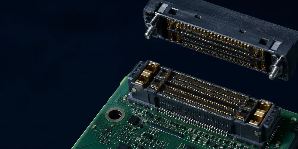
Choosing a board-to-board connector by pin count alone can create power-integrity, signal-integrity, and upgrade problems. A robust pin budget starts with the interface list, then allocates contacts for power, returns, high-speed pairs, control signals, shielding/grounding, manufacturing test, and reasonable future margin.
Key Takeaways
- Build the pin budget from functions and current paths, not from a convenient standard circuit count.
- Count differential-pair grounds, power returns, sequencing, shields, test access, and no-connect positions explicitly.
- Add spare contacts only where a credible future use exists; reserve their schematic and layout intent.
- Recheck connector size, mating force, breakout routing, and assembly sequence after the electrical count is complete.
Quick Planning Framework
| Pin Group | Planning Question |
|---|---|
| Power | How many rails and how much current per rail? |
| Ground / return | What return current and high-speed reference paths are required? |
| High-speed pairs | How many lanes/clocks and what pin-field rules apply? |
| Low-speed control | GPIO, I²C, SPI, UART, reset, enable, interrupts? |
| Analog | Which signals need quiet return paths or separation? |
| Test / service | Programming, debug, identification, detect pins? |
| Margin | What changes are plausible in the next board revision? |
1. Create a Signal Inventory First
Start from the schematic interface rather than selecting a convenient connector size.
A pin-budget worksheet should include:
- net name;
- signal direction;
- voltage domain;
- maximum current;
- signal type (single-ended, differential, analog, power);
- required return/ground strategy;
- sequencing requirement;
- whether the pin is mandatory, optional, or reserved.
This turns “we need about 40 pins” into a traceable engineering requirement.
2. Power Pins Are Determined by Current, Not Rail Count
One voltage rail may need several connector contacts. The number depends on the current rating under the real thermal conditions and on the desired voltage drop.
If multiple pins are paralleled, account for:
- connector derating with adjacent contacts energized;
- unequal current sharing;
- PCB copper and via resistance;
- contact aging and temperature;
- fault and peak current.
Do not allocate one pin per rail unless the current is genuinely low enough for the selected contact system.
3. Ground Pins Have Multiple Jobs
Ground contacts provide power return and high-speed reference continuity. They may also reduce coupling between sensitive signals.
The correct ground allocation depends on:
- total return current;
- pin-field topology;
- high-speed differential-pair arrangement;
- analog isolation needs;
- EMI/EMC strategy;
- connector supplier guidance.
A simple fixed rule such as “one ground for every four signals” is not universally valid.
4. Differential Interfaces Consume More Than Two Contacts
A differential pair itself uses two conductors, but the connector may need nearby ground contacts and specific pin assignment to meet channel performance.
Examples include:
- PCIe;
- USB;
- Ethernet;
- SATA/SAS;
- MIPI;
- proprietary SerDes links.
At high data rates, use the connector’s recommended pin map or simulation model where available. The pin budget should reserve the complete high-speed channel pattern, not just the two signal pins.
5. Example: Camera/Imaging Module
A camera-module connector might include:
| Function | Example Allocation |
|---|---|
| High-speed data lanes | 8 signal contacts for four differential lanes |
| Differential clock | 2 |
| I²C control | 2 |
| Reset / enable / interrupt | 2–4 |
| Power rails | Multiple contacts depending on current |
| Ground / return | Multiple contacts based on power and SI needs |
| ID / detect / spare | 1–4 |
The exact total depends on the interface standard and connector pin-field recommendations. That is why a “camera always needs 24 pins” rule is too rigid.
6. How Much Spare Capacity Should You Add?
A flat 20% margin is a useful early estimate, but final spare allocation should be intentional.
Add spare contacts when:
- the module is expected to evolve;
- additional GPIO or sensing is plausible;
- extra ground pins may be required after SI/EMI testing;
- alternate power rails may be introduced;
- debug/service access is valuable.
Avoid excessive margin when connector width, cost, mating force, and routing density are critical.
A better rule is: reserve enough contacts for realistic change, not an arbitrary percentage.
7. Pin Count vs Connector Size
Pitch alone does not determine connector length because row count, housing margins, guide features, and retention hardware consume space. When comparing 40-, 80-, or 120-position connectors, use the mechanical drawings and actual keep-out zones.
Also consider whether two smaller connectors are preferable to one large connector.
One large connector
Advantages
- one mating operation;
- simpler BOM;
- centralized interface.
Risks
- higher total mating force;
- larger concentrated footprint;
- greater sensitivity to board flex and alignment.
Multiple smaller connectors
Advantages
- flexible placement;
- can separate power, analog, and high-speed domains;
- may reduce routing congestion.
Risks
- more tolerance stacks to control;
- risk of partial mating or incorrect assembly sequence;
- higher component count.
8. Standard Circuit Counts
Manufacturers usually offer discrete circuit-count options within each series. Do not assume that every multiple of 10 is available or that two brands share the same options.
The correct workflow is:
- calculate the electrical pin budget;
- define minimum spare/ground requirements;
- shortlist connector families that meet pitch and stack height;
- check the actual available circuit counts;
- select the next suitable standard option;
- update the schematic pin assignment and mechanical model.
9. Final Pin-Count Checklist
- All power rails included with current-based contact count.
- Ground/return contacts allocated for PI and SI.
- Differential lanes include required reference/ground strategy.
- Control and reset signals included.
- Analog pins separated where necessary.
- Debug, detect, and identification pins considered.
- Future margin justified.
- Actual circuit count confirmed in the selected series.
- Total mating force and board flex reviewed for high pin counts.
GSCONN Selection Support
For GSCONN connector selection, provide the completed pin budget together with pitch, stack height, electrical ratings, mating orientation, operating environment, and board-space limits. The final circuit count should be chosen from the current product range and verified on the product drawing.
FAQ
Should I always add 20% spare pins?
No. Use 20% only as an early planning estimate. Final margin should reflect realistic future functions, grounding needs, and board-space constraints.
Can unused pins be left completely unassigned?
Usually yes, but high-speed pin fields may benefit from strategic grounding. Follow the connector and interface recommendations.
Is one 100-pin connector better than two 50-pin connectors?
Neither is universally better. Compare routing, mating force, alignment, fault isolation, assembly sequence, and board space.
Related reading:
- High-Density Board-to-Board Connector Guide
- High-Current Board-to-Board Power Connector Guide
- PCB Board-to-Board Connector Design Guide
Technical References
- Samtec SEARAY 0.80 mm high-density arrays
- Molex board-to-board connector portfolio
- GSCONN board-to-board connector portfolio
Related reading on GSConn
- Wire-to-Board vs Board-to-Board Connectors
- Industrial USB Connector Guide
- IP67 vs IP68 USB Connector
- Stacked USB Connector Guide
- Request a Quote
Engineering references
- Product drawing, datasheet, material declaration and qualification report for the selected connector series
- IPC land-pattern and acceptability guidance applicable to the PCB assembly class
- Project-specific vibration, shock, thermal and electrical requirements