
High-Current Board-to-Board Power Connectors: Design and Selection Guide
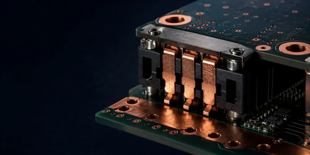
High-current board-to-board interconnects must be selected as part of the power-distribution system, not as ordinary signal connectors with larger pins. Contact resistance, temperature rise, copper distribution, current sharing, airflow, ambient temperature, mating reliability, fault current, and connector derating all influence the usable current.
Key Takeaways
- A catalog current rating is meaningful only with its test conditions and derating information.
- The complete current path—contact, termination, vias, planes, and busbar—must be evaluated thermally.
- Parallel contacts do not share current perfectly; validate the assembled system at worst-case ambient and airflow.
- Live mating, fault current, creepage, clearance, and touch protection are separate requirements from continuous current.
Quick Reference
| Application Need | Typical Connector Architecture | Key Design Check |
|---|---|---|
| Power plus signals in one interface | Hybrid power/signal connector | Power-pin temperature rise and signal return paths |
| Board-to-board power module | Dedicated power blades or high-current contacts | Current sharing and board copper |
| Server / data-center power | High-current card-edge or power array | Thermal rise, airflow, hot-plug requirements |
| Busbar-to-board connection | Floating pin/socket or busbar interface | Misalignment and touch-safe spacing |
| Very high current | Busbar-based interconnect | Joint resistance and mechanical retention |
1. Start With Temperature Rise, Not Nominal Current
A connector’s published current rating is valid only under defined test conditions. In a real enclosure, adjacent energized contacts, reduced airflow, high ambient temperature, PCB copper limitations, and contact aging can raise the operating temperature.
The basic loss relationship is:
Power loss = I² × R
For one contact, even a few milliohms matter at high current. For example:
| Contact Resistance | 10 A | 20 A | 40 A |
|---|---|---|---|
| 2 mΩ | 0.2 W | 0.8 W | 3.2 W |
| 5 mΩ | 0.5 W | 2.0 W | 8.0 W |
| 10 mΩ | 1.0 W | 4.0 W | 16.0 W |
These values illustrate why temperature-rise data and derating curves are more useful than a single headline current number.
2. Real High-Power Board Interconnects Cover a Wide Range
Commercial board-level power products span from a few amperes per circuit to hundreds of amperes in specialized architectures. For example, TE Connectivity publishes high-density card-edge power products with high per-contact current capability for data-center power systems, while Molex offers Sentrality pin-and-socket interconnects for board-to-board, busbar-to-board, and busbar-to-busbar applications at much higher current levels.
As concrete reference points—not interchangeable design targets—TE lists 24 A per contact for its High-Density card-edge family, while Molex lists Sentrality options up to 350 A for specialized single-circuit architectures. These ratings come from very different contact systems and must not be compared without considering termination, thermal conditions, voltage, and application geometry.
The important engineering lesson is that pitch alone does not determine current rating. Contact geometry, conductor material, plating, contact force, PCB copper, airflow, and allowable temperature rise all matter.
3. Hybrid vs Dedicated Power Connectors
Hybrid power + signal
Hybrid connectors combine large power contacts with smaller signal contacts. They reduce connector count and can simplify module assembly, but require deliberate pin assignment so that high-current paths do not compromise sensitive signals.
Use them when:
- power and control must mate simultaneously;
- board area is limited;
- sequencing or sensing contacts are required;
- one serviceable interface is preferable to separate power and signal connectors.
Dedicated power connector
A dedicated power connector simplifies thermal analysis and can provide larger contact cross-section, more copper around the termination, and better creepage/clearance options.
Use it when:
- current dominates the interface;
- power loss must be minimized;
- high-voltage spacing is important;
- modular power supplies or busbars are involved.
4. Parallel Contacts Need Current-Sharing Analysis
Designers often parallel several contacts to carry more current. This can work, but current does not split perfectly. Small differences in contact resistance, trace length, copper geometry, or mating force can cause one pin to run hotter than the others.
For parallel power contacts:
- use symmetric copper paths where possible;
- avoid forcing all current through one narrow neck before the connector;
- provide sufficient vias between copper layers;
- place return contacts to minimize loop area;
- review the manufacturer’s multi-contact derating data;
- measure temperature rise on the assembled product under worst-case load.
Do not simply multiply a single-contact current rating by the number of contacts.
5. PCB Copper Can Become the Limiting Element
A connector rated for high current can still overheat if the PCB feeding it is undersized. Review:
- outer- and inner-layer copper thickness;
- trace/plane width;
- via count and finished hole diameter;
- via current sharing;
- thermal spreading area;
- local component heat sources;
- airflow direction;
- connector contact-to-pad transition geometry.
For very high current, a busbar, copper coin, heavy-copper PCB, or direct busbar-to-connector architecture may be more appropriate than relying on standard PCB traces.
6. Voltage, Creepage, Clearance, and Hot-Plug
High current does not necessarily mean high voltage, but power connectors often carry both. Verify the selected product’s voltage rating and application-specific creepage/clearance requirements.
If the connector will mate under load, also check whether the system requires:
- first-mate/last-break contacts;
- pre-charge or sequencing;
- anti-arcing geometry;
- touch-safe protection;
- hot-plug qualification;
- fault-current coordination.
A connector that is safe for static power transfer is not automatically suitable for repeated live mating.
7. Selection Checklist
| Question | Why It Matters |
|---|---|
| What is continuous and peak current? | Determines thermal and transient stress |
| How many contacts are energized together? | Affects derating |
| What is maximum ambient temperature? | Reduces thermal margin |
| What copper feeds the connector? | Can limit current before the contact does |
| Is airflow available? | Strongly affects temperature rise |
| Is mating under load allowed? | Changes connector requirements |
| What is the required cycle life? | Affects contact system choice |
| Is board or busbar misalignment expected? | May justify floating power contacts |
GSCONN Selection Support
For a GSCONN board-level power project, define current, voltage, contact count, board spacing, mating direction, environment, and mechanical tolerance before requesting a recommendation. Final current capability should be confirmed from the applicable datasheet and validated with system-level temperature-rise testing.
FAQ
Is lower contact resistance always better?
Yes for conduction loss, but it is only one selection parameter. Thermal path, contact force, plating durability, housing material, and PCB copper also affect reliability.
Can I double current by using two contacts in parallel?
Not automatically. Parallel contacts require derating and current-sharing analysis because resistance and copper paths are never perfectly identical.
When should I move from PCB traces to a busbar?
When current density, temperature rise, voltage drop, board area, or efficiency targets make conventional PCB copper impractical.
Related reading:
Technical References
- TE Connectivity High-Density card-edge power connectors
- Molex Sentrality pin-and-socket interconnects
- IPC-2152 current-carrying-capacity standard
Related reading on GSConn
- Wire-to-Board vs Board-to-Board Connectors
- Industrial USB Connector Guide
- IP67 vs IP68 USB Connector
- Stacked USB Connector Guide
- Request a Quote
Engineering references
- Product drawing, datasheet, material declaration and qualification report for the selected connector series
- IPC land-pattern and acceptability guidance applicable to the PCB assembly class
- Project-specific vibration, shock, thermal and electrical requirements