
Coplanar Board-to-Board Connectors: In-Line PCB Connection Guide
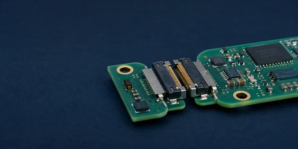
A coplanar board-to-board connection joins two printed circuit boards in approximately the same plane instead of stacking them vertically. This geometry is useful when a product must extend a PCB assembly laterally, join modular panels, connect adjacent control boards, or avoid the height of a mezzanine stack.
Key Takeaways
- Coplanar describes the relative PCB orientation, not a single connector construction.
- Board-edge datums, mating travel, and the complete tolerance stack usually drive reliability more than nominal pitch.
- Floating interfaces are valuable when chassis tolerance, vibration, or thermal growth could side-load the contacts or solder joints.
- Final selection must still account for signal integrity, power distribution, retention, and service access.
Quick Geometry Comparison
| Connection Geometry | Board Relationship | Typical Connector Approach | Common Use |
|---|---|---|---|
| Coplanar | Same plane, edge-to-edge | Coplanar B2B, card-edge, right-angle pair, floating connector | Modular panels, adjacent PCBs |
| Mezzanine | Parallel, face-to-face | Stacking header/receptacle | Compute modules, compact electronics |
| Perpendicular | Approximately 90° | Right-angle B2B or backplane connector | Daughter cards, front panels |
| Floating | Geometry varies | Floating B2B interface | Misalignment, vibration, thermal movement |
1. What “Coplanar” Means in Connector Design
The term describes the board geometry, not one universal connector type. Two PCBs can be connected coplanarly using several architectures:
- dedicated coplanar plug-and-receptacle systems;
- card-edge contacts;
- right-angle headers and sockets;
- board-to-board jumpers;
- floating connectors designed to absorb assembly tolerance.
This distinction matters because electrical density, serviceability, board gap, and mechanical tolerance can differ substantially between architectures.
2. Why Choose a Coplanar Connection?
Coplanar layouts are attractive when the design needs to extend across a wide or flat mechanical envelope.
Advantages
- avoids vertical board stacking;
- can simplify access to components on both PCBs;
- supports modular replacement of adjacent boards;
- can reduce thermal shadowing between stacked boards;
- works well for tiled or segmented electronics.
Constraints
- board-edge position and connector datum become critical;
- wide assemblies can accumulate dimensional tolerance;
- rigid interfaces may transmit chassis movement into solder joints;
- the design must reserve mating travel and edge clearance.
Therefore, coplanar is not inherently better than mezzanine. It solves a different packaging problem.
3. Common Coplanar Connector Architectures
Dedicated coplanar board-to-board connector
These connectors are designed so the mating interfaces meet near the PCB edges. They can provide a compact, serviceable connection but require precise control of board spacing and mating direction.
Card-edge connector
The edge of one PCB becomes the contact interface and mates with a socket on the adjacent assembly. Card-edge systems can support high circuit counts and straightforward module replacement, but the edge-finger geometry, plating, bevel, board thickness, and insertion path must follow the connector specification.
Right-angle header and receptacle
A pair of right-angle connectors can join adjacent PCBs. This is a practical approach for lower-density interfaces, but connector body dimensions and board-edge clearance must be considered early in the mechanical design.
Floating coplanar connector
A floating connector allows controlled movement between the fixed PCB solder joints and the mating interface. This can help absorb X/Y misalignment, thermal expansion, and chassis tolerance. The allowed float is product-specific and must remain unobstructed by nearby components or enclosure features.
4. Board Gap and Tolerance Stack
A frequent failure mode is designing the nominal board gap correctly but ignoring manufacturing tolerance.
Build a tolerance stack that includes:
- PCB outline tolerance;
- connector placement tolerance;
- housing dimensional tolerance;
- chassis or standoff tolerance;
- board bow and twist;
- thermal expansion;
- allowed connector self-alignment or float.
For rigid coplanar systems, small lateral errors can cause high mating force or incomplete engagement. For floating systems, the mechanism only works if the PCB layout and enclosure leave enough travel.
5. Electrical Considerations
Coplanar geometry does not remove normal signal-integrity and power-integrity requirements.
For high-speed signals:
- preserve a continuous return path to the connector;
- keep differential breakout short and symmetric;
- avoid unnecessary via stubs;
- use the connector vendor’s S-parameter model when available;
- review pin assignment for crosstalk and ground distribution.
For power:
- size contacts and PCB copper for temperature rise;
- distribute return contacts appropriately;
- validate current sharing when multiple contacts are paralleled.
6. Mechanical Design Considerations
| Design Item | What to Check |
|---|---|
| Mating travel | Can the boards move far enough to fully mate/unmate? |
| Edge clearance | Are housings and latches clear of the PCB edge? |
| Connector alignment | Are assembly datums controlled? |
| Board support | Will mating force bend the PCB? |
| Retention | Are solder joints carrying excessive structural load? |
| Service access | Can a technician release the boards without damaging them? |
For long tiled systems, floating connectors can be particularly valuable because thermal expansion and frame tolerance accumulate across the assembly.
7. Applications
Coplanar B2B connections are commonly considered for:
- LED and display modules;
- adjacent control and I/O boards;
- industrial sensor modules;
- modular instrumentation;
- panel electronics;
- automotive or transportation electronics where tolerance management is important;
- segmented backplane or edge-connected assemblies.
The final connector style should be chosen from the electrical, mechanical, environmental, and service requirements—not from board orientation alone.
GSCONN Selection Support
GSCONN identifies board-to-board connectors as part of its connector portfolio and offers engineering selection support. For a coplanar design, provide PCB thickness, board-edge gap, circuit count, current/voltage, mating direction, expected misalignment, vibration level, and service-cycle requirements so the connector can be evaluated against the actual tolerance stack.
FAQ
Is a card-edge connector always coplanar?
No. Card-edge describes the contact architecture. The connected boards can be arranged in different mechanical orientations depending on the socket and chassis design.
Do coplanar connectors eliminate board-height constraints?
They avoid a vertical board stack, but the connector body, latching features, and mating travel still require mechanical clearance.
When is a floating connector preferable?
When PCB placement, chassis tolerances, vibration, or thermal expansion could otherwise create side load at the connector interface.
Related reading:
- PCB Board-to-Board Connector Design Guide
- Low-Profile Board-to-Board Connector Guide
- SMT Board-to-Board Connector Guide
Technical References
- Samtec flexible board-stacking orientations
- GCT board-to-board connector orientation and profile filters
- GSCONN board-to-board connector portfolio
Related reading on GSConn
- Wire-to-Board vs Board-to-Board Connectors
- Industrial USB Connector Guide
- IP67 vs IP68 USB Connector
- Stacked USB Connector Guide
- Request a Quote
Engineering references
- Product drawing, datasheet, material declaration and qualification report for the selected connector series
- IPC land-pattern and acceptability guidance applicable to the PCB assembly class
- Project-specific vibration, shock, thermal and electrical requirements