
Custom USB Connector: OEM/ODM Solutions Guide
Custom USB Connector: OEM/ODM Solutions Guide
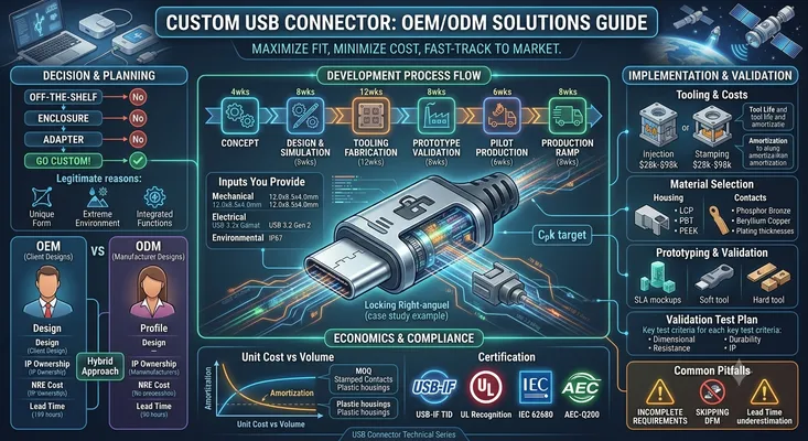
When 10,000 off-the-shelf USB connectors do not fit your design, it is time to consider custom. Here is what the process looks like, what it costs, and how to avoid the mistakes that turn a 12-week project into a 12-month nightmare.
Table of Contents
- When Does Custom Make Sense
- OEM vs ODM: Know the Difference
- The Custom Connector Development Process
- Design Inputs You Must Provide
- Tooling: The Biggest Cost Driver
- Material Selection for Custom Connectors
- Prototyping and Validation
- MOQ and Volume Economics
- Certification for Custom Connectors
- Common Pitfalls and How to Avoid Them
- Case Study: Custom Right-Angle USB-C with Locking
- FAQ
When Does Custom Make Sense
Custom USB connectors are not for everyone. The tooling investment alone starts at $5,000 and can exceed $50,000 for complex designs. Before committing, exhaust the standard options.
The Decision Tree
Can you find an off-the-shelf connector that meets your requirements?
├── Yes → Buy it. Do not customize.
└── No → Is the mismatch mechanical, electrical, or both?
    ├── Mechanical only → Can you modify the enclosure instead?
    │   ├── Yes → Modify the enclosure.
    │   └── No → Consider custom.
    └── Electrical → Can you add an adapter board?
        ├── Yes → Use an adapter board.
        └── No → Custom is justified.
Legitimate Reasons to Go Custom
| Reason | Example | Annual Volume Threshold |
|---|---|---|
| Unique form factor | Connector must fit a 4 mm × 6 mm envelope | 5,000+ |
| Integrated functionality | USB-C + power + CAN bus in one connector | 10,000+ |
| Proprietary locking | Competitor-proof mechanical interface | 20,000+ |
| Brand differentiation | Custom shell color, logo, shape | 50,000+ |
| Extreme environment | 200°C, 1,000g shock, deep-sea pressure | 1,000+ (specialized market) |
| Obsolete replacement | Form-fit-function replacement for EOL part | 500+ (no alternative exists) |
When Custom Is a Mistake
- Volume under 2,000 units/year: The tooling amortization per unit will be higher than the connector itself
- Purely cosmetic changes: Overmolding a standard connector with a custom boot is cheaper than custom tooling
- You have not checked all manufacturers: Molex, Amphenol, TE, JAE, Hirose, GCT, and a dozen others each have thousands of SKUs. Your “impossible” requirement may exist in a catalog you have not searched.
OEM vs ODM: Know the Difference
These terms are used interchangeably in connector sourcing, but they mean different things with different cost and IP implications.
| Aspect | OEM (Original Equipment Manufacturer) | ODM (Original Design Manufacturer) |
|---|---|---|
| Who designs? | You provide the design | Manufacturer designs based on your requirements |
| Who owns the tooling? | You (usually) | Manufacturer (usually) |
| Who owns the IP? | You | Shared or manufacturer-owned |
| NRE cost | Higher ($20k–$100k+) | Lower ($5k–$30k) |
| Per-unit cost | Lower at high volume | Higher per unit (manufacturer margin on design) |
| Lead time | Longer (16–30 weeks) | Shorter (8–16 weeks) |
| Design control | Full control | Limited — manufacturer makes design choices |
| Best for | Proprietary, high-volume, long-lifecycle products | Moderate volume, faster time-to-market |
The Hybrid Approach
Many companies use a hybrid: contract a design firm to create the connector design and drawings, then bid the manufacturing to multiple connector factories. This gives you IP ownership and competitive per-unit pricing, at the cost of managing two vendors instead of one.
The Custom Connector Development Process
A typical custom USB connector project follows this timeline:
| Phase | Duration | Activities | Deliverables |
|---|---|---|---|
| Requirements definition | 2–4 weeks | Define electrical, mechanical, environmental specs | Product Requirement Document (PRD) |
| Conceptual design | 4–6 weeks | 3D modeling, material selection, DFM review | 3D CAD model, preliminary BOM |
| Detailed design | 4–8 weeks | Tolerance analysis, mold flow simulation, signal integrity simulation | 2D drawings, final BOM, tooling design |
| Tooling fabrication | 6–12 weeks | Mold making, stamping die fabrication, plating line setup | First-article tooling samples |
| Prototype validation | 4–8 weeks | Dimensional inspection, electrical testing, environmental testing | Test reports, approval sign-off |
| Pilot production | 4–6 weeks | Process validation, CPK studies, production line qualification | PPAP/FAI documentation |
| Production ramp | 4–8 weeks | Yield optimization, capacity verification | Production-ready process |
Total: 28–52 weeks for a full-custom connector from concept to production. Plan accordingly — this is not a last-minute fix for a design problem discovered during prototype bring-up.
Design Inputs You Must Provide
The manufacturer cannot read your mind. Provide these inputs explicitly, in writing, with tolerances.
Mechanical Requirements
| Parameter | Why It Matters | Example |
|---|---|---|
| Envelope dimensions (L × W × H) | Defines the maximum connector size | 12.0 × 8.5 × 4.0 mm |
| PCB footprint constraints | Determines pin layout and pitch | 0.5 mm pitch, 2-row, 12 positions |
| Mating face location | Positions the connector relative to the enclosure | Centerline 3.25 mm above PCB surface |
| Mating force target | Affects contact design and user experience | Insertion 5–20 N, extraction 8–20 N |
| Mounting method | Determines mechanical retention strategy | 2× TH tabs + 4× SMT anchors |
| Cable strain relief requirement | Affects overmold design | 90° bend, 500 cycles, 50 N pull force |
Electrical Requirements
| Parameter | Why It Matters | Example |
|---|---|---|
| Protocol support | Determines pin count and signal routing | USB 3.2 Gen 2 (10 Gbps) + PD 3.0 (100W) |
| Differential impedance | Critical for high-speed signal integrity | 85Ω ± 10% |
| Current rating per contact | Determines contact cross-section and plating | VBUS: 5A continuous, 8A peak |
| Voltage rating | Determines creepage/clearance distances | 20V nominal, 100V dielectric withstand |
| Contact resistance (initial) | Baseline for quality and life prediction | ≤30 mΩ per VBUS contact |
| Insulation resistance | Leakage current specification | ≥100 MΩ at 100 VDC |
Environmental Requirements
| Parameter | Why It Matters | Example |
|---|---|---|
| Operating temperature range | Determines material selection (LCP vs PBT, gold thickness) | -40 to +85°C |
| IP rating | Drives sealing design and gasket material | IP67 (1m immersion, 30 min) |
| Mating cycle life | Determines contact plating thickness and spring design | 10,000 cycles |
| Vibration profile | Affects contact normal force and locking mechanism | 10–2000 Hz, 20g, 3 axes |
| Chemical exposure | Determines housing material compatibility | Diesel fuel, isopropyl alcohol, UV exposure |
| Salt spray / corrosion | Drives plating specification and shell material | 96 hours salt spray per IEC 60068-2-11 |
Tooling: The Biggest Cost Driver
What Tooling You Are Paying For
| Tool | Purpose | Cost Range | Lead Time |
|---|---|---|---|
| Plastic injection mold (housing) | Forms the connector body and tongue | $5,000–25,000 | 6–10 weeks |
| Plastic injection mold (secondary) | Overmold, strain relief, inserts | $3,000–10,000 | 4–8 weeks |
| Stamping die (contacts) | Progressive die for contact terminals | $8,000–30,000 | 8–12 weeks |
| Stamping die (shell) | Forms the metal outer shell | $5,000–15,000 | 6–10 weeks |
| Insert molding tool | Overmolds contacts into plastic body | $3,000–8,000 | 4–8 weeks |
| Assembly fixtures | Positioning and pressing fixtures for production | $2,000–5,000 | 3–6 weeks |
| Test fixtures | Electrical and mechanical test jigs | $2,000–5,000 | 3–6 weeks |
Total tooling: $28,000–98,000 for a full-custom USB-C connector.
Tool Life and Amortization
| Tool Type | Typical Life (Shots/Cycles) | Replacement Cost (% of original) |
|---|---|---|
| Plastic injection mold (steel) | 500,000–1,000,000 shots | 70–85% |
| Plastic injection mold (aluminum) | 50,000–100,000 shots | 40–60% (but shorter life) |
| Stamping die (carbide) | 10,000,000+ cycles | 80–90% |
| Stamping die (tool steel) | 1,000,000–5,000,000 cycles | 70–85% |
For a connector with 4 cavities per mold, a 500,000-shot steel mold produces 2 million connectors before requiring refurbishment. At 50,000 units/year, that is 40 years of production — far exceeding the product lifecycle. Tooling cost per unit at this volume: $0.01–0.05.
Cost-Saving Strategies
- Use existing contact geometries. If the manufacturer has an existing USB-C contact design that meets your electrical requirements, you save the stamping die cost entirely.
- Aluminum prototype molds. For initial validation (100–500 pieces), aluminum molds cost 40–60% less than steel and can be produced in 3–4 weeks. Switch to steel for production.
- Family molds. Combine multiple small parts into a single mold base, sharing the mold base cost across multiple components.
- Modify an existing design. Starting from an existing connector and modifying the shell or mounting features is far cheaper than a clean-sheet design.
Material Selection for Custom Connectors
Housing Materials
| Material | Temp Range | Dielectric Strength | Cost Index | Best For |
|---|---|---|---|---|
| LCP (liquid crystal polymer) | -40 to +240°C | 30 kV/mm | 100 (baseline) | High-temp, high-frequency, precision parts |
| PBT (polybutylene terephthalate) | -30 to +120°C | 20 kV/mm | 40–60 | Cost-sensitive consumer products |
| PA66 (nylon 66) | -30 to +100°C | 18 kV/mm | 50–70 | Good mechanical strength, moderate temp |
| PPA (polyphthalamide) | -40 to +180°C | 25 kV/mm | 80–100 | Automotive under-hood applications |
| PEEK | -60 to +260°C | 20 kV/mm | 500–800 | Extreme environment, aerospace |
Recommendation: LCP is the default for USB-C connectors because it flows well into thin-walled sections (the 0.6 mm tongue wall), has low moisture absorption (<0.02%), and maintains dimensional stability through reflow soldering (260°C peak). Use PBT only for USB 2.0-only, non-reflow applications.
Contact Materials
| Material | Conductivity (% IACS) | Spring Properties | Cost Index |
|---|---|---|---|
| Phosphor bronze (C52100) | 13% | Excellent | 60–80 |
| Beryllium copper (C17200) | 22% | Superior | 200–300 |
| Brass (C26000) | 28% | Poor | 30–50 |
Recommendation: Phosphor bronze for most applications — good spring properties, reasonable cost, widely available. Beryllium copper for high-cycle-life (>20k) or high-temperature applications. Never use brass for spring contacts — it will relax permanently after the first few insertions.
Contact Plating
| Plating | Thickness | Wear Life | Cost Index | Best For |
|---|---|---|---|---|
| Gold flash over nickel | 0.05–0.1 μm Au | <500 cycles | 50–70 | Disposable products |
| 15μ” gold over nickel | 0.38 μm Au | 5,000 cycles | 100 (baseline) | Consumer electronics |
| 30μ” gold over nickel | 0.76 μm Au | 10,000+ cycles | 130–150 | Industrial, high-reliability |
| 50μ” gold over nickel | 1.27 μm Au | 20,000+ cycles | 180–220 | Military, aerospace |
| Palladium-nickel (PdNi) + gold flash | 0.8 μm PdNi + 0.1 μm Au | 10,000+ cycles | 120–140 | Automotive, high-temp |
Prototyping and Validation
Prototype Stages
| Stage | Quantity | Purpose | Typical Duration |
|---|---|---|---|
| SLA/3D printed mockups | 5–10 pcs | Form/fit check, enclosure integration | 1–2 weeks |
| Soft tool samples (aluminum mold) | 50–200 pcs | Functional testing, initial electrical validation | 4–6 weeks |
| Hard tool samples (steel mold) | 200–500 pcs | Full validation, compliance testing | 8–12 weeks |
| Pilot production | 1,000–5,000 pcs | Process capability, yield verification | 6–8 weeks |
Validation Test Plan
| Test | Standard | Sample Size | Pass Criteria |
|---|---|---|---|
| Dimensional inspection | Per drawing | 30 pcs | Cpk ≥ 1.33 for critical dimensions |
| Contact resistance | IEC 60512-2-1 | 30 pcs | ≤30 mΩ initial, ≤50 mΩ after environmental |
| Insulation resistance | IEC 60512-3-1 | 10 pcs | ≥100 MΩ |
| Dielectric withstand | IEC 60512-4-1 | 10 pcs | No breakdown at 100 VAC for 1 minute |
| Mating cycle durability | IEC 60512-9-1 | 5 pcs | Contact resistance ≤50 mΩ after 10,000 cycles |
| Thermal shock | IEC 60068-2-14 | 10 pcs | No cracks, contact resistance ≤50 mΩ |
| Mixed flowing gas | IEC 60068-2-60 | 10 pcs | Contact resistance ≤50 mΩ after 4-day exposure |
| Salt spray | IEC 60068-2-11 | 5 pcs | No base metal corrosion after 96 hours |
| Vibration | IEC 60068-2-6 | 5 pcs | No discontinuity >1 μs |
| Solderability | IEC 60068-2-58 | 10 pcs | ≥95% wetting after steam aging |
MOQ and Volume Economics
Minimum Order Quantities
| Component | Typical MOQ | Reason |
|---|---|---|
| Custom plastic housing | 10,000–50,000 pcs | Mold setup and material minimums |
| Custom stamped contacts (reel-to-reel) | 50,000–100,000 pcs | Stamping die setup, plating line minimum |
| Custom shell | 10,000–50,000 pcs | Progressive die setup |
| Complete connector assembly | 5,000–20,000 pcs | Assembly line setup |
| Custom cable assembly | 1,000–5,000 pcs | Cable procurement and assembly setup |
Unit Cost vs Volume
For a mid-complexity custom USB-C connector (16-pin, USB 3.2, SMT + TH hybrid, stainless steel shell):
| Annual Volume | Tooling Amortization/Unit | Material + Labor/Unit | Total Unit Cost |
|---|---|---|---|
| 5,000 | $6.00 ($30k tooling) | $1.20 | $7.20 |
| 10,000 | $3.00 | $1.05 | $4.05 |
| 25,000 | $1.20 | $0.85 | $2.05 |
| 50,000 | $0.60 | $0.72 | $1.32 |
| 100,000 | $0.30 | $0.62 | $0.92 |
| 500,000 | $0.06 | $0.48 | $0.54 |
Break-even vs off-the-shelf: If an off-the-shelf connector costs $1.50 and your custom connector costs $1.32 at 50k volume, you save $0.18/unit — or $9,000/year. Against $30,000 tooling, the payback is 3.3 years. Not compelling unless the custom connector enables a product feature that drives revenue.
Certification for Custom Connectors
USB-IF Certification
Custom USB connectors can and should be submitted for USB-IF certification. The process:
- Join USB-IF as an adopter ($4,000/year for a vendor membership)
- Submit samples to an authorized independent test lab (ITL)
- Pass the compliance test suite: electrical, mechanical, environmental
- Receive a TID (Test ID) — this is the proof of compliance
- List on the Integrators List at usb.org
Cost: $3,000–8,000 for testing, plus membership fee. Allow 8–12 weeks.
Other Certifications
| Certification | Applicability | Cost Estimate | Timeline |
|---|---|---|---|
| USB-IF TID | Any product using USB logo | $7,000–12,000 (incl. membership) | 8–12 weeks |
| UL Recognition | Products sold in North America | $5,000–15,000 | 8–16 weeks |
| IEC 62680 (EU Common Charger) | Products sold in EU | $3,000–8,000 | 6–10 weeks |
| AEC-Q200 (automotive) | Automotive passive components | $10,000–30,000 | 12–24 weeks |
Common Pitfalls and How to Avoid Them
Pitfall 1: Incomplete Requirements
The problem: You tell the manufacturer “I need a USB-C connector that is waterproof and handles 100W.” They deliver a connector that is waterproof and handles 100W — but the mounting tab spacing does not match your PCB, the height is 0.5 mm off, and it requires a 0.8 mm PCB when you are using 1.6 mm.
The fix: Provide a complete PRD with dimensioned drawings, electrical specifications with tolerances, environmental test conditions, and your PCB stackup and enclosure model. The manufacturer can only design to what you tell them.
Pitfall 2: Skipping DFM Review
The problem: Your mechanical engineer designs a beautiful connector in SolidWorks. The mold maker looks at it and says “this cannot be molded” — undercuts, wall thicknesses below minimum, no draft angles.
The fix: Involve the manufacturer’s tooling engineer during the conceptual design phase, not after detailed design is complete. A 30-minute DFM review at week 4 saves 12 weeks of redesign at week 20.
Pitfall 3: Underestimating Lead Time
The problem: You budget 16 weeks for a custom connector. At week 14, the first mold trial produces parts with sink marks. The mold needs modification — add 4 weeks. Then the plating adhesion fails — add 3 weeks. Your product launch slips by 2 months.
The fix: Budget 32–40 weeks for a full-custom connector. If it finishes early, great. If not, your schedule has buffer. Communicate the realistic timeline to your program manager before they commit to a launch date.
Pitfall 4: No Second Source
The problem: Your custom connector is produced by a single factory. That factory has a fire, a labor dispute, or a quality crisis. Your production line stops.
The fix: If your volume exceeds 50,000 units/year, qualify a second source during the pilot production phase. This requires dual tooling (another $30k–100k), but the supply chain resilience is worth it for high-volume products. For lower volumes, maintain 6 months of safety stock.
Pitfall 5: Ignoring End-of-Life Planning
The problem: Five years into production, your custom connector manufacturer discontinues the plating process you specified. You need to requalify a new plating — 12 weeks and $5,000. Then you discover the mold is worn and needs refurbishment — another 8 weeks and $15,000.
The fix: Build tooling maintenance and requalification into your product lifecycle plan. Budget for mold refurbishment every 500,000 shots. Maintain relationships with at least two plating suppliers qualified for your specification.
Case Study: Custom Right-Angle USB-C with Locking
Scenario: A manufacturer of portable medical diagnostic devices needed a USB-C connector that was:
– Right-angle, mid-mount, with a 1.0 mm PCB
– IP67 sealed at the enclosure interface
– Screw-locking for secure connection in ambulance environments
– USB 3.2 Gen 1 (5 Gbps) + PD 3.0 (60W)
– 10,000 mating cycles
– Annual volume: 15,000 units
Off-the-shelf search: No standard connector combined right-angle mid-mount, IP67, and screw locking. The closest options were panel-mount screw-locking connectors, but they required internal cabling that degraded signal integrity.
Solution: Custom connector developed with a Shenzhen-based connector manufacturer.
Timeline:
– Requirements and concept: 6 weeks
– Detailed design and DFM: 8 weeks
– Tooling (steel molds, 4 cavities): 10 weeks
– Prototype validation: 6 weeks
– Pilot production: 4 weeks
– Total: 34 weeks
Cost:
– NRE (tooling + design): $42,000
– Per-unit cost at 15k/year: $3.85
– USB-IF certification: $8,500
– First-year total: $108,250 ($7.22/unit amortized)
Outcome: The custom connector enabled a product feature (ambulance-ready, waterproof, locking USB-C) that became a key differentiator in a competitive market. The per-unit premium of ~$3.50 over a standard connector was absorbed by a $200 higher ASP for the “ruggedized” product variant.
FAQ
Q: What is the smallest volume at which custom USB connectors are economically viable?
Approximately 5,000 units/year, assuming a tooling cost of $30,000 amortized over 3 years ($2/unit) and a per-unit cost of $1.50. Total: $3.50/unit. Below this, the tooling amortization per unit becomes disproportionate to the connector’s BOM cost.
Q: Can I patent a custom USB connector design?
Yes, if the design is novel and non-obvious. Design patents cover the ornamental appearance; utility patents cover functional innovations (e.g., a new locking mechanism). USB connectors with standard electrical interfaces but unique mechanical features are patentable. Consult a patent attorney before disclosing your design to manufacturers.
Q: How do I protect my IP when working with Chinese manufacturers?
- File patents and design registrations in China before engaging manufacturers
- Use NDAs with penalty clauses enforceable under Chinese law
- Split the tooling across multiple suppliers (mold maker ≠ stamper ≠ assembler)
- Own the tooling outright — do not let the manufacturer claim ownership through “tooling amortization” agreements
- Conduct periodic audits of the manufacturer’s other customers to detect IP leakage
Q: What is the difference between “custom” and “modified standard”?
A modified standard connector starts from an existing design with minor changes — different shell color, longer mounting tabs, custom logo. NRE is typically $2,000–10,000 and lead time is 8–16 weeks. A full custom connector is a clean-sheet design. Know which one you need before approaching manufacturers.
Q: Do custom USB connectors require USB-IF certification?
If you use the USB logo or claim USB compliance, yes. If you call it a “proprietary data connector with USB-compatible pinout,” technically no — but this marketing approach limits your customer base and may violate USB-IF trademark guidelines. In practice, any connector marketed as USB should be certified.
This article is part of the USB Connector Technical Series. For related topics, see our guides on How to Choose the Right USB Type-C Connector, USB Connector Manufacturer Selection, and USB Locking Connectors.