
Renewable Energy Connector Guide: Solar, Wind, and Energy Storage
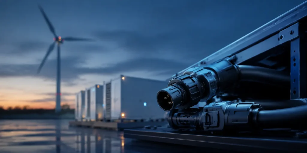
Renewable-energy connectors must deliver electrical safety and low resistance across years of UV, moisture, salt, thermal cycling, vibration, and difficult maintenance. Application location is the first filter: a PV string connector, nacelle control connector, offshore interface, and battery-rack power connector solve very different problems.
Quick Reference
| Application | Connector Type | IP Rating | Key Requirement |
|---|---|---|---|
| Solar PV string | MC4-style DC connector | IP67/IP68 | High voltage (1500V DC), UV resistance |
| Solar inverter | AC/DC power connector | IP65–IP67 | High current, locking |
| Wind turbine (nacelle) | Heavy-duty circular | IP67/IP68 | Vibration, salt, temperature |
| Offshore wind (subsea) | Marine circular / subsea connector | IP68 | Saltwater, pressure, 25yr life |
| Energy storage (ESS) | High-current power connector | IP65–IP67 | High current, thermal |
| Battery rack interconnect | B2B or bus bar | — | High current, vibration |
| Solar tracker / BMS | M12 or sealed wire-to-board | IP67 | Signal + low power |
1. Why Energy Connectors Are Different
Renewable energy systems expose connectors to conditions that exceed industrial norms:
| Environment | Solar (PV farm) | Onshore Wind | Offshore Wind |
|---|---|---|---|
| Temperature | -30 to +85°C | -40 to +70°C | -20 to +60°C (sea) |
| UV exposure | Extreme (direct sun, decades) | High | High (above water) |
| Salt spray | Low (inland) | Moderate | Extreme (constant) |
| Vibration | Low | High (turbine) | High + wave motion |
| Humidity | Moderate | High | Saturated |
| Life expectancy | 25+ years | 20+ years | 25+ years |
| Service access | Difficult (field) | Difficult (tower) | Extremely difficult (subsea) |
The 25-year life requirement is the defining factor. Energy connectors must survive decades of UV, thermal cycling, and moisture — with zero maintenance access.
2. Solar PV Connectors
MC4-Style DC Connector
The universal standard for PV module interconnection. “MC4” is a Stäubli trademark, but the form factor is widely used as the PV industry standard.
| Parameter | Specification |
|---|---|
| Voltage | Up to 1500V DC |
| Current | 30–60A (depends on wire gauge) |
| Wire | 2.5–10mm² (solar cable) |
| IP rating | IP67/IP68 (mated) |
| Locking | Snap lock + optional locking clip |
| UV | UV-stabilized housing (outdoor 25yr) |
| Contact | Tin-plated copper (anti-corrosion) |
Key Selection Factors
| Factor | Why It Matters |
|---|---|
| UV-stabilized housing | Standard PA degrades in 3–5 years of direct sun |
| Tin-plated contacts | Silver/copper corrode from humidity ingress |
| Mating torque | Loose MC4 connections are a fire risk (high DC current) |
| Certified for 1500V | 1000V systems are being phased to 1500V |
3. Wind Turbine Connectors
Onshore (Nacelle and Tower)
| Location | Connector | Requirement |
|---|---|---|
| Nacelle control | M12 / industrial circular | Vibration, -40°C |
| Slip ring interface | Slip ring connector | Continuous rotation |
| Power conversion (AC) | Heavy-duty circular | High current, vibration |
| Tower cabling | Rectangular heavy-duty | High voltage AC |
| Yaw/brake control | M12 or sealed connectors | Signal, vibration |
Offshore (Subsea)
Offshore wind subsea connectors must survive:
– Constant saltwater exposure — 316 stainless, titanium, or specially coated shells
– Hydrostatic pressure (at seabed depth)
– 25-year design life without maintenance
Subsea connectors are a specialized category (wet-mate/dry-mate) — significantly more expensive than standard industrial connectors.
4. Energy Storage System (ESS) Connectors
Battery energy storage (ESS) uses high-current connectors for cell-to-cell, module-to-rack, and rack-to-system:
| Connection | Current | Connector |
|---|---|---|
| Cell tap (BMS sense) | 0.5–2A | Wire-to-board, sealed |
| Module power (internal) | 20–50A | Bus bar or high-current B2B |
| Rack power | 50–200A | Power connector / bus bar |
| System DC bus | 200–800A | Bus bar (not connector) |
| Communication (CAN/RS485) | Signal | M12 or RJ45 industrial |
Thermal management is critical: ESS connectors at 50–200A generate significant heat. Match current rating, derate for grouping, and verify thermal performance.
5. Lifetime and Procurement Checklist
Define maximum system voltage, continuous and fault current, conductor size, touch safety, connector interoperability policy, UV exposure, salt and chemical exposure, thermal cycling, vibration, altitude, installation tooling, inspection access, and target service life. Require traceable test evidence for the exact mated pair and cable configuration. In PV systems, avoid mixing connectors from different manufacturers unless the combination is explicitly evaluated and approved.
6. GSConn Renewable Energy Connectors
| Series | Application | Features |
|---|---|---|
| EN-PV-MC4 | Solar PV string | MC4-style, 1500V, IP68, UV-stabilized |
| EN-ESS-150 | ESS rack power | 150A, gold/tin, locking, IP65 |
| CIR-M12-IP67 | Wind turbine control | M12 A/D-coded, IP67, vibration-proof |
| EN-MAR | Offshore / marine | 316 stainless, IP68, salt spray tested |
| EN-BMS | BMS signal | Sealed wire-to-board, IP67 |
GSConn renewable energy connectors cover solar PV (MC4-style, 1500V), ESS power (up to 150A), wind turbine control (M12), and marine/offshore (316 stainless). UV-stabilized housings, salt-spray tested, and 25-year design life. Test reports and material certifications available.
Related reading:
– Circular Connector Selection Guide
– High-Power EV Charging Connector Guide
– Sealed vs Unsealed Connectors