
USB Combo Connector: Combining USB with HDMI, Ethernet, and More
USB Combo Connector: Combining USB with HDMI, Ethernet, and More
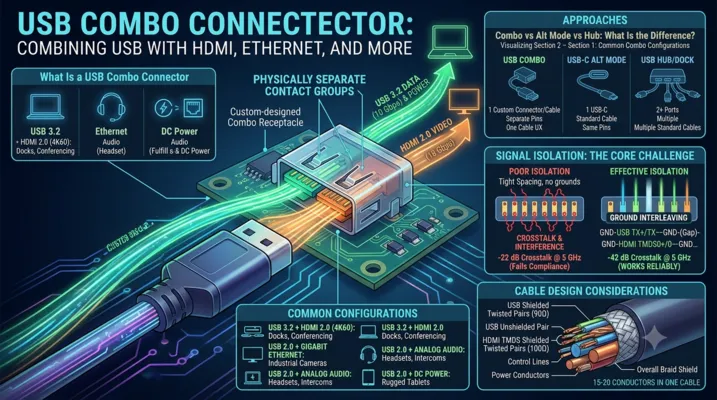
Why use two connectors when one can do both jobs? USB combo connectors merge USB data and power with HDMI, Ethernet, audio, or DC power into a single physical interface — saving space, reducing BOM count, and simplifying the user experience. But combining high-speed interfaces in one connector body is an engineering challenge with no free lunch.
Table of Contents
- What Is a USB Combo Connector
- Common Combo Configurations
- Signal Isolation: The Core Challenge
- USB + HDMI Combos
- USB + Ethernet Combos
- USB + Audio Combos
- USB + DC Power Combos
- Custom Multi-Protocol Connectors
- PCB Layout for Combo Connectors
- Cable Design Considerations
- Application Examples
- FAQ
What Is a USB Combo Connector
A USB combo connector integrates USB data and power with one or more additional interfaces — HDMI, Ethernet, audio, or DC power — into a single physical connector body. The user plugs in one cable and gets multiple functions.
This is different from USB-C Alternate Mode, where a single USB-C connector carries multiple protocols over the same physical pins. A combo connector has physically separate contact sets for each interface, sharing only the connector housing and, optionally, the cable assembly.
Combo vs Alt Mode vs Hub: What Is the Difference
| Approach | Physical Connectors | Protocols | Cable | User Experience |
|---|---|---|---|---|
| USB-C Alt Mode | 1 (USB-C) | USB + DP/HDMI over same pins | Standard USB-C cable | One cable, but requires Alt Mode support on both ends |
| USB combo connector | 1 (custom housing) | USB + HDMI/Ethernet/audio over separate pins | Custom combo cable | One cable, no Alt Mode required |
| USB hub / dock | 2+ (USB-C + HDMI + Ethernet) | Each connector handles its own protocol | Multiple standard cables | Multiple cables, standard connectors |
When a Combo Connector Makes Sense
- Space constraints: Your enclosure has room for exactly one connector opening, but you need USB + HDMI
- User simplicity: One cable to connect, no “which port does what” confusion
- Ruggedization: One sealed connector penetration is easier to waterproof than three
- Proprietary ecosystem: You want a unique connector that locks customers into your cable ecosystem
- Cable management: Reducing cable count in a vehicle, aircraft, or medical cart
When It Does Not
- You can use USB-C Alt Mode instead: USB-C already supports DisplayPort and HDMI Alt Mode. If your application only needs USB + video, a standard USB-C port with Alt Mode support achieves the same result with standard cables.
- Volume is low (<5,000/year): Custom combo connectors require custom tooling. The NRE is not amortizable at low volume.
- Users need standard cable compatibility: If users expect to plug in a standard USB cable or standard HDMI cable, a combo connector prevents that.
Common Combo Configurations
| Combo Type | Interfaces Combined | Typical Pin Count | Applications |
|---|---|---|---|
| USB 2.0 + HDMI 1.4 | 4 USB + 19 HDMI = 23 pins | 25–30 (with grounds) | Kiosks, digital signage, thin clients |
| USB 3.2 + HDMI 2.0 | 9 USB + 19 HDMI = 28 pins | 35–45 (with grounds) | Laptop docks, conferencing systems |
| USB 2.0 + Ethernet (10/100) | 4 USB + 8 Ethernet = 12 pins | 16–20 (with grounds) | POS terminals, industrial HMIs |
| USB 2.0 + Audio (stereo + mic) | 4 USB + 4 audio = 8 pins | 12–16 (with grounds) | Headsets, intercom panels |
| USB 2.0 + DC power | 4 USB + 2 power = 6 pins | 8–12 (with grounds) | Rugged tablets, handheld instruments |
| USB 3.2 + Ethernet (GigE) | 9 USB + 8 Ethernet = 17 pins | 25–30 (with grounds) | Industrial cameras, machine vision |
| USB 2.0 + HDMI + DC power | 4 USB + 19 HDMI + 2 power = 25 pins | 35–40 (with grounds) | All-in-one docking connectors |
Signal Isolation: The Core Challenge
When you put USB 3.2 (10 Gbps differential pairs) next to HDMI 2.0 (18 Gbps TMDS pairs) in the same connector body, crosstalk is not a theoretical concern — it is a guarantee unless the connector is designed for isolation.
Crosstalk Mechanisms in Combo Connectors
| Mechanism | Description | Mitigation |
|---|---|---|
| Capacitive coupling | Electric field coupling between adjacent contacts | Ground pins between signal groups, increased contact spacing |
| Inductive coupling | Magnetic field coupling between current-carrying contacts | Orthogonal orientation of sensitive pairs, shielding |
| Common impedance | Shared ground return paths create voltage noise | Dedicated ground returns per interface, low-inductance ground plane |
| Connector shell resonance | The metal shell acts as a cavity resonator at GHz frequencies | Absorptive materials, segmented shell design |
Isolation Design Strategies
1. Physical separation: The simplest and most effective strategy. Leave at least 2–3 empty pin positions between the USB contact group and the HDMI/Ethernet contact group. This increases connector width but dramatically reduces crosstalk.
2. Ground interleaving: Place ground pins between every high-speed differential pair. For a USB 3.2 + HDMI combo: GND-TX+-TX–GND-RX+-RX–GND-(gap)-GND-TMDS0+-TMDS0–GND-TMDS1+-TMDS1–GND-…
3. Shielded contact modules: Some high-end combo connectors use individual shielded modules for each protocol, with metal dividers between modules. This is the best-performing but most expensive approach.
4. Differential signaling: All high-speed interfaces in a combo connector should use differential signaling (USB 3.2, HDMI, Ethernet). Single-ended signals (USB 2.0 D+/D-, I2C, UART) are far more susceptible to crosstalk and should be placed farthest from high-speed pairs.
Measured Crosstalk Performance
For a well-designed USB 3.2 Gen 2 + HDMI 2.0 combo connector with ground interleaving and 1.5 mm contact pitch:
| Frequency | USB-to-HDMI Crosstalk | USB Spec Limit |
|---|---|---|
| 1 GHz | -55 dB | -40 dB |
| 5 GHz | -42 dB | -35 dB |
| 10 GHz | -35 dB | -30 dB |
With poor isolation (no ground interleaving, 0.8 mm pitch):
| Frequency | USB-to-HDMI Crosstalk | USB Spec Limit |
|---|---|---|
| 1 GHz | -35 dB | -40 dB |
| 5 GHz | -22 dB | -35 dB |
| 10 GHz | -15 dB | -30 dB |
The difference between “works reliably” and “fails compliance” is a few ground pins.
USB + HDMI Combos
This is the most common combo configuration, driven by thin laptops and tablets that need external display connectivity but lack space for a full-size HDMI port.
Design Options
| Option | Connector Size (approx.) | HDMI Version | USB Version | Best For |
|---|---|---|---|---|
| Micro-HDMI + Micro-USB side-by-side | 18 × 7 mm | 1.4 (1080p) | 2.0 | Low-cost tablets, SBCs |
| Custom slim combo | 22 × 6 mm | 2.0 (4K60) | 3.2 Gen 1 | Ultra-thin laptops |
| Custom rugged combo | 30 × 10 mm | 2.0 (4K60) | 3.2 Gen 2 | Industrial panel PCs |
| USB-C with HDMI Alt Mode | Standard USB-C (8.3 × 2.6 mm) | 1.4 (4K30) via Alt Mode | 3.2 / USB4 | Mainstream laptops (not a combo connector per se) |
The HDMI Alt Mode Question
USB-C HDMI Alt Mode allows a USB-C port to output HDMI signals directly, using the SuperSpeed pairs for TMDS data and the SBU lines for HDMI control signals (DDC, CEC, HPD). This eliminates the need for a combo connector — a single standard USB-C port handles both USB data and HDMI output.
Why use a physical combo connector instead of Alt Mode?
- Simultaneous USB 3.2 + HDMI: HDMI Alt Mode consumes the SuperSpeed pairs, leaving only USB 2.0 data. A physical combo connector provides independent USB 3.2 and HDMI channels simultaneously.
- HDMI 2.0 bandwidth: HDMI Alt Mode over USB-C is limited to HDMI 1.4b (~10.2 Gbps). HDMI 2.0 (18 Gbps) requires more bandwidth than USB-C Alt Mode can provide.
- No Alt Mode negotiation: Some embedded systems cannot implement the full USB PD and Alt Mode protocol stack. A physical combo connector uses fixed pin assignments with no negotiation.
USB + Ethernet Combos
Combining USB and Ethernet in one connector is common in industrial equipment, POS terminals, and embedded systems where a single cable provides both data connectivity and device power.
Design Considerations
Ethernet magnetics: Standard Ethernet (10/100/1000BASE-T) requires isolation transformers at each end of the link. These magnetics are bulky — a typical Gigabit Ethernet transformer module is 15 × 10 × 6 mm. For a combo connector, you have three options:
- Magnetics in the connector: Some manufacturers integrate the Ethernet magnetics into the connector body. This saves PCB space but increases connector size and cost.
- Magnetics on the PCB: The connector carries Ethernet signals directly to PCB-mounted magnetics. More PCB area but smaller connector.
- ** Capacitive isolation**: For short-reach applications (<10m), capacitive isolation chips (e.g., TI DP83826) replace magnetics with smaller, cheaper capacitors. Not IEEE 802.3 compliant but functional for many embedded applications.
PoE compatibility: If the Ethernet link carries Power over Ethernet (48V), the combo connector must provide sufficient creepage distance between the PoE pins and the USB VBUS pins. This typically requires at least 2.0 mm creepage for 48V — difficult in a compact combo connector.
Typical Implementation
Pinout (USB 2.0 + 10/100 Ethernet, 16-pin):

1  - VBUS
2  - D-
3  - D+
4  - GND (USB)
5  - GND (isolation)
6  - GND (isolation)
7  - TX+
8  - TX-
9  - GND (Ethernet)
10 - GND (Ethernet)
11 - RX+
12 - RX-
13 - GND (isolation)
14 - GND (isolation)
15 - Shield (USB)
16 - Shield (Ethernet)
Note the double ground pins between the USB and Ethernet sections. These create a low-impedance isolation barrier that prevents Ethernet common-mode noise from coupling into the USB data lines.
USB + Audio Combos
USB + 3.5 mm audio combo connectors were common on smartphones before the industry moved to USB-C audio. They persist in niche applications: aviation headsets, intercom panels, assistive listening devices, and industrial communication terminals.
Design Considerations
Analog vs digital audio: The combo connector can carry either:
– Analog audio: Left, right, microphone, and ground — 4 additional pins. Simple, no codec required on the accessory side.
– Digital audio (I2S): BCLK, LRCLK, DATA, MCLK — 4–5 pins. Requires a codec in the accessory, but immune to analog noise.
Ground isolation: Analog audio is exquisitely sensitive to ground noise. The USB VBUS return current flowing through a shared ground pin creates a voltage drop that appears as audible buzz (at 1 kHz for USB 2.0 microframes, or 8 kHz for USB 3.2). The audio ground must be isolated from the USB power ground, joining only at a single star-ground point on the PCB.
ESD protection: Audio jacks are notorious ESD entry points — a user touching the plug tip can discharge several kV directly into the audio codec input. The combo connector must include ESD protection diodes on all audio pins, not just the USB data lines.
USB + DC Power Combos
Some industrial and rugged devices use a combo connector that carries USB data plus a separate DC power input — typically 12V or 24V at several amps for system power, with USB handling only data.
Why Not Just Use USB PD?
USB PD can deliver up to 240W (48V/5A), which covers most portable device power requirements. But there are cases where a separate DC power path makes sense:
- Power > 240W: Industrial equipment needing 500W+ cannot use USB PD
- Fixed voltage requirement: Some systems need a regulated 12V or 24V rail that USB PD’s variable voltage cannot guarantee without an additional DC-DC converter
- No PD controller: Ultra-simple embedded systems may not implement the USB PD protocol stack
- Hot-swap battery charging: Direct DC input bypasses USB negotiation for faster battery charging
Design Requirements
| Parameter | Requirement | Reason |
|---|---|---|
| Contact rating | 10A+ for power pins | DC power can be 5–20A |
| Creepage distance | ≥3.0 mm at 48V, ≥5.0 mm at 100V | Safety isolation from USB data pins |
| Contact sequencing | Power pins mate first, break last | Prevents arcing during hot-plug |
| Contact resistance | ≤10 mΩ per power pin | Minimizes I²R heating at high current |
| Wire gauge | 16–20 AWG for power conductors | Acceptable voltage drop over 2–3m cable |
Custom Multi-Protocol Connectors
For truly unique requirements, a fully custom multi-protocol connector may be the only solution. This is a significant engineering investment.
Design Process
- Define the pin count and protocol mix. USB 2.0 or 3.2? HDMI or DisplayPort? Ethernet speed? Power requirements?
- Create the contact arrangement. Work with a connector manufacturer to arrange the contacts with appropriate spacing, ground isolation, and sequencing.
- Simulate signal integrity. Full 3D EM simulation of the connector + PCB launch + cable assembly is essential for any design with >5 Gbps signals.
- Design the cable assembly. The connector is only half the solution — the cable must maintain signal integrity, manage power delivery, and survive the target mechanical environment.
- Validate to all applicable standards. USB-IF for the USB portion, HDMI Licensing for HDMI, IEEE 802.3 for Ethernet, and any industry-specific standards (MIL-STD, AEC, IEC 60601 for medical).
Cost and Timeline
| Scope | NRE Cost | Timeline | Annual Volume for Viability |
|---|---|---|---|
| Simple (USB 2.0 + power + audio) | $25,000–50,000 | 24–36 weeks | 10,000+ |
| Medium (USB 3.2 + HDMI) | $50,000–100,000 | 36–48 weeks | 25,000+ |
| Complex (USB4 + HDMI 2.1 + Ethernet + power) | $100,000–250,000 | 48–72 weeks | 50,000+ |
PCB Layout for Combo Connectors
General Principles
- Keep signal groups together. All USB signals on one side of the connector, all HDMI on the other. Do not interleave.
- Ground plane continuity. The ground plane under the connector must be unbroken. Do not route any traces through the connector footprint area on the ground plane layer.
- Via stitching. Place a ring of ground vias around the connector footprint, spaced at λ/10 of the highest frequency (e.g., 3 mm spacing for 10 GHz).
- No high-speed traces under the connector. Route all traces away from the connector footprint on the top layer, dropping to inner layers only after clearing the connector body.
Connector-Specific Considerations
| Combo Type | Special Layout Requirement |
|---|---|
| USB + HDMI | Separate ground pours for USB and HDMI ground returns, joined at a single point |
| USB + Ethernet | Ethernet magnetics placement: as close to the connector as possible, <25 mm |
| USB + Audio | Audio traces on a quiet PCB layer, away from switching regulators and USB traces |
| USB + DC power | Power traces: wide (>2 mm per amp), on outer layers for heat dissipation, star-ground connection |
Cable Design Considerations
The cable for a combo connector is more complex than the connector itself. A USB + HDMI combo cable must carry:
– Two USB 3.2 SuperSpeed pairs (shielded twisted pairs, 90Ω differential)
– One USB 2.0 pair (unshielded twisted pair, 90Ω differential)
– Four HDMI TMDS pairs (shielded twisted pairs, 100Ω differential)
– HDMI control signals (DDC, CEC, HPD, 5V — unshielded)
– USB VBUS and GND (power conductors, typically 20–24 AWG)
– Overall shield
This is 15–20 conductors in a single cable. Cable diameter is typically 6–8 mm — thick by consumer standards but acceptable for industrial and professional applications.
Cable Design Checklist
- [ ] Differential impedance controlled to ±10% for all high-speed pairs
- [ ] Each shielded pair has its own foil shield + drain wire
- [ ] Power conductors sized for ≤0.5V drop at maximum current over maximum cable length
- [ ] Overall braid shield with ≥85% coverage
- [ ] Overmolded strain relief at both ends, tested to ≥500 flex cycles
- [ ] Cable jacket material appropriate for the environment (PVC for indoor, PUR for industrial, TPE for medical)
Application Examples
Digital Signage Kiosk
Requirement: Single-cable connection between a media player and a display in a public kiosk. Cable is routed through a narrow articulated arm — only one connector fits through the arm conduit.
Solution: USB 2.0 + HDMI 1.4 combo connector
– USB provides touchscreen data and firmware updates
– HDMI provides 1080p video
– Custom overmolded cable assembly, 2m length, with 90° connector on the display end
– IP54 sealed at the kiosk penetration
Industrial Machine Vision Camera
Requirement: GigE Vision camera on a robotic arm. Space for one connector. Cable must survive 1 million flex cycles.
Solution: USB 2.0 + Gigabit Ethernet combo connector
– Ethernet for video streaming (GigE Vision protocol)
– USB 2.0 for camera configuration and firmware updates
– High-flex cable with PUR jacket, tested to 5 million flex cycles (5× safety factor)
– Screw-locking connector for vibration resistance
Medical Patient Monitor
Requirement: Bedside monitor with a single-cable connection to a wall-mounted hub. Cable must be cleanable with hospital disinfectants, IP67 at the connector.
Solution: USB 2.0 + DC power combo connector
– USB for data (vital signs, alarms) to the hospital network via the hub
– 24V DC power from the hub — no battery in the monitor
– Push-pull locking, IP67 sealed
– Silicone cable jacket (disinfectant-resistant, biocompatible per ISO 10993)
Aviation In-Seat Entertainment
Requirement: Passenger seat connector for personal device charging + audio for in-flight entertainment. Must be damage-resistant (passengers are rough on connectors) and impossible to disassemble (no loose parts that could become FOD).
Solution: USB 2.0 + stereo audio combo connector
– USB provides 15W charging (5V/3A)
– Analog audio provides in-flight entertainment audio to passenger headphones
– Recessed mounting with tamper-resistant bezel
– 30μ” gold contacts for corrosion resistance in the cabin environment
FAQ
Q: Can I use a standard USB-C connector as a combo connector by reassigning pins?
No. USB-C has a fixed pin assignment defined by the USB-IF specification. Reassigning pins to carry non-USB protocols (e.g., using the SBU lines for Ethernet) will create interoperability failures with standard USB-C devices and cables. If a user plugs in a standard USB-C cable, the non-standard pin assignment could damage either the device or the cable. Use USB-C Alt Mode for alternate protocols — it is the standards-compliant way to carry multiple protocols over USB-C.
Q: Do combo connectors require separate certification for each protocol?
Yes. A USB + HDMI combo connector must pass USB-IF compliance testing for the USB portion and HDMI compliance testing for the HDMI portion. Each certification is independent and has its own cost and timeline. Budget for both.
Q: What is the maximum practical number of protocols in one combo connector?
Three is the practical limit for most designs. Beyond three, the connector becomes too large, the cable becomes too thick, and crosstalk isolation becomes exponentially harder. The most common three-protocol combo is USB + HDMI + DC power.
Q: Can I use a combo connector with a standard cable by making one side of the combo compatible with a standard plug?
Some manufacturers offer “split” combo connectors where the receptacle is physically two standard connectors (e.g., USB-C and HDMI) in a shared housing with a single mounting footprint. This lets the user plug in either a combo cable or two standard cables. The trade-off is a larger connector footprint — but it provides maximum flexibility.
Q: How do I handle ESD protection for a combo connector with multiple protocols?
Each protocol’s pins require ESD protection appropriate for that protocol’s voltage levels and data rates:
– USB 2.0 D+/D-: 5V ESD diode, ≤3 pF capacitance
– USB 3.2 SuperSpeed pairs: 3.3V ESD diode, ≤0.5 pF capacitance
– HDMI TMDS pairs: 3.3V ESD diode, ≤0.5 pF capacitance
– Ethernet: 3.3V ESD diode, ≤3 pF (10/100) or ≤1 pF (GigE)
– Audio: 5V ESD diode, capacitance not critical (<50 pF)
Do not use a single ESD protection array for all pins — the capacitance requirements for high-speed pairs are incompatible with the voltage requirements for power pins. Use separate protection devices per protocol group.
This article is part of the USB Connector Technical Series. For related topics, see our guides on Custom USB Connector OEM/ODM, USB Type-C Complete Guide, and USB PCB Design Guidelines.