
USB Locking Connector: Secure Connection Solutions
USB Locking Connector: Secure Connection Solutions
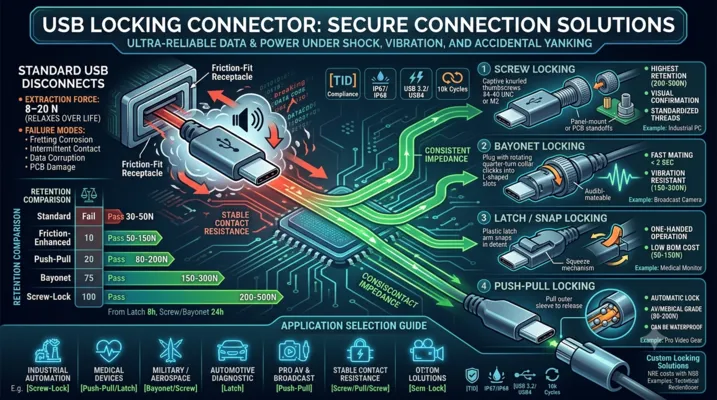
Standard USB connectors are designed to disconnect. When your application demands the opposite — a connection that stays put under vibration, shock, and accidental yanking — locking USB connectors are the answer.
Table of Contents
- Why Standard USB Connectors Disconnect
- Locking Mechanism Types
- Screw Locking (USB with Thumbscrews)
- Bayonet Locking
- Latch / Snap Locking
- Push-Pull Locking
- Custom Locking Solutions
- Mechanical Performance Comparison
- Electrical Performance with Locking Connectors
- Application Selection Guide
- Panel Mount vs PCB Mount Locking
- FAQ
Why Standard USB Connectors Disconnect
Standard USB connectors rely on friction for retention. The USB-C specification defines an extraction force of 8–20 N — enough to hold the cable under its own weight and gentle handling, but not enough to survive real-world abuse.
How Much Retention Do You Actually Need?
| Environment | Typical Cable Pull Force | Standard USB-C OK? |
|---|---|---|
| Office desk, laptop | 1–5 N (gravity + light tug) | Yes |
| Factory floor, walking past | 10–30 N (snagging on clothing/equipment) | Marginal — will disconnect occasionally |
| Vehicle, vibration | 5–50 N peak (road shock, cable weight × acceleration) | No — will disconnect frequently |
| Heavy equipment | 50–200 N (operator pulling, cable snagging) | No — connector will be damaged |
| Military field deployment | 50–500 N (deliberate yank, cable as trip hazard) | No — catastrophic failure likely |
The 8–20 N extraction force is a design target, not a guarantee. After 1,000 mating cycles, the retention force of a standard USB-C connector drops by 30–50% as the spring contacts relax and the plastic tongue wears. A connector that barely held at 10 N when new will disconnect at 5 N after a year of use.
Failure Modes Beyond Disconnection
| Failure Mode | Cause | Consequence |
|---|---|---|
| Intermittent contact | Vibration breaks the wipe contact momentarily | Data corruption, PD renegotiation loops |
| Fretting corrosion | Micro-motion between contacts oxidizes the gold surface | Contact resistance rises from 30 mΩ to >1Ω |
| Connector body damage | Repeated partial disconnection + re-insertion under load | Tongue cracks, shell deforms |
| PCB damage | Cable yank transfers force through SMT pads | Pad lift, trace fracture |
Locking Mechanism Types
Five primary locking mechanisms exist for USB connectors, each with distinct trade-offs in retention force, ease of use, cost, and compatibility.
| Type | Retention Force | Mating Speed | Tool-Free? | Standard Cable Compatible? | Cost Premium |
|---|---|---|---|---|---|
| Screw locking | 200–500 N | Slow | Yes | No (requires locking cable) | 3–5× |
| Bayonet locking | 150–300 N | Fast | Yes | No | 4–6× |
| Latch / snap | 50–150 N | Very fast | Yes | No (requires locking plug) | 2–3× |
| Push-pull | 80–200 N | Fast | Yes | No | 3–4× |
| Friction-enhanced | 30–50 N | Instant | Yes | Yes | 1.2–1.5× |
Screw Locking (USB with Thumbscrews)
Screw locking is the most common and most reliable locking mechanism. It uses two thumbscrews (typically #4-40 UNC or M2 thread) on the cable plug that thread into standoffs on the receptacle or panel.
How It Works
The cable plug has two captive thumbscrews on either side of the USB connector body. These screws engage with threaded inserts on the receptacle panel or PCB-mounted standoffs. When tightened to 0.3–0.5 N·m, the screws generate 200–500 N of clamping force — far exceeding any accidental pull force.
Design Variants
| Variant | Thread | Panel Thickness | Typical Use |
|---|---|---|---|
| Standard D-Sub style | #4-40 UNC | 1.5–3.0 mm panel | Industrial PCs, test equipment |
| Metric | M2 × 0.4 | 1.0–2.5 mm panel | European equipment, medical devices |
| PCB standoff | #4-40 or M2 | N/A (screws into PCB standoff) | Embedded systems, single-board computers |
| Jackscrew | #4-40 UNC | 1.5–3.0 mm panel | MIL-spec applications |
Advantages
- Highest retention force of any locking mechanism
- Visual confirmation — you can see that the screws are tightened
- Standardized threads — compatible with existing cable assemblies and panel designs
- Fail-safe — even if one screw loosens, the other retains the connection
Disadvantages
- Slow mating/unmating — 5–10 seconds to connect or disconnect
- Requires access — you need finger clearance on both sides to turn the thumbscrews
- Overtightening risk — excessive torque can strip threads or crack the panel
- Not blind-mate — operator must align the connector before tightening screws
Bayonet Locking
Bayonet locking uses a spring-loaded rotating collar on the cable plug that engages with pins or ramps on the receptacle. A quarter-turn locks or unlocks the connection.
How It Works
The receptacle has three radial pins (or ramps) spaced 120° apart. The cable plug collar has matching L-shaped slots. To connect: align, push, and rotate ~90°. Spring force inside the collar keeps the pins seated in the locked position. To disconnect: push slightly, rotate opposite direction, pull.
Advantages
- Very fast connect/disconnect — under 2 seconds
- Blind-mate capable — the operator does not need visual access
- Audible/tactile feedback — the spring-loaded collar clicks into place
- Vibration resistant — spring preload prevents loosening under vibration
Disadvantages
- Proprietary interface — bayonet USB connectors are not standardized; each manufacturer has their own design
- Higher cost — precision-machined collar and spring mechanism
- Bulkier — the collar adds 6–10 mm to the connector diameter
- Limited suppliers — fewer options compared to screw locking
Applications
Bayonet locking USB is common in military communications equipment, broadcast cameras, and aerospace test systems where operators need to connect and disconnect frequently in confined spaces.
Latch / Snap Locking
Latch locking uses a spring-loaded latch on the cable plug that snaps into a detent on the receptacle. A squeeze-to-release mechanism disengages the latch.
How It Works
The cable plug has a molded plastic latch arm (similar to an RJ45 connector but larger). When inserted, the latch flexes and snaps into a recess in the receptacle shell. To remove, the operator squeezes the latch release and pulls.
Advantages
- Fastest connect/disconnect — under 1 second
- One-handed operation — squeeze and pull
- Low cost — molded plastic latch adds minimal BOM cost
- Compact — adds only 2–3 mm to connector height
Disadvantages
- Lower retention force — 50–150 N, enough for most industrial but not military
- Latch fatigue — plastic latch arms can break after 5,000–10,000 cycles
- Snag risk — the protruding latch can catch on cables and clothing
- Not waterproof — the latch mechanism creates an additional ingress path
Applications
Latch-locking USB is common in medical devices (patient monitors, infusion pumps), point-of-sale terminals, and handheld industrial scanners where one-handed operation is essential.
Push-Pull Locking
Push-pull locking uses an internal spring-loaded ball or collet mechanism. Pushing the cable plug in locks it automatically; pulling the outer sleeve back releases it.
How It Works
The receptacle has an internal groove. The cable plug has spring-loaded balls or a collet that expands into this groove when the plug is fully inserted. To disconnect, the operator pulls back on a sliding outer sleeve, which retracts the locking elements.
Advantages
- Automatic locking — no additional action after insertion
- Smooth exterior — no protruding levers or screws to snag
- Good retention — 80–200 N depending on design
- Can be waterproof — the smooth barrel design accepts O-ring seals
Disadvantages
- Complex mechanism — more parts, higher manufacturing cost
- Wear over time — ball detents and collet springs fatigue
- Requires two hands — one to hold the device, one to pull the sleeve
- Not standardized — each manufacturer has a proprietary design
Applications
Push-pull USB connectors are popular in medical imaging equipment, laboratory instruments, and professional audio/video gear where quick, secure connections are needed and cable snagging is a hazard.
Custom Locking Solutions
When off-the-shelf locking connectors do not meet your requirements, custom solutions are viable at moderate volumes.
Common Customizations
| Customization | Typical NRE Cost | Minimum Order | Lead Time |
|---|---|---|---|
| Custom latch geometry for specific retention force | $2,000–5,000 | 5,000 units | 8–12 weeks |
| Custom screw pattern or thread size | $1,000–3,000 | 2,000 units | 6–10 weeks |
| Overmolded cable assembly with locking plug | $3,000–8,000 | 1,000 assemblies | 10–14 weeks |
| Integrated locking + IP68 sealing | $5,000–15,000 | 3,000 units | 12–18 weeks |
When Custom Makes Sense
- Your volume exceeds 10,000 units/year, amortizing NRE over a reasonable per-unit cost
- Your mechanical constraint cannot be met by any standard locking connector
- You need a proprietary locking mechanism to prevent unauthorized disconnection
- You need locking combined with other features (waterproofing, EMI shielding, custom cable length)
Mechanical Performance Comparison
Retention Force by Mechanism
| Mechanism | Initial Retention (N) | Retention After 5k Cycles | Vibration Resistance |
|---|---|---|---|
| Standard USB-C (no lock) | 10–20 | 5–12 | Poor |
| Friction-enhanced | 25–50 | 18–35 | Marginal |
| Latch / snap | 80–150 | 50–100 | Good |
| Push-pull | 100–200 | 70–150 | Good |
| Bayonet | 150–300 | 120–250 | Excellent |
| Screw locking (#4-40) | 300–500 | 250–450 | Excellent |
Vibration Test Results
Per MIL-STD-202G Method 204, Test Condition D (20g, 10–2000 Hz):
| Connector Type | Result | Notes |
|---|---|---|
| Standard USB-C | Fail at 2 hours | Intermittent contact >1 μs, contact resistance drift >100 mΩ |
| Latch locking | Pass 8 hours | Contact resistance drift <50 mΩ |
| Screw locking | Pass 24 hours | No measurable change in contact resistance |
| Bayonet locking | Pass 24 hours | No measurable change in contact resistance |
Electrical Performance with Locking Connectors
Locking mechanisms do not fundamentally change the electrical interface — the contacts are still standard USB pinout. However, locking improves electrical performance in two ways:
1. Stable Contact Resistance
Under vibration, standard USB connectors experience micro-motion between contacts. Each micro-motion cycle removes a few nanometers of gold plating through fretting. Over time, contact resistance increases from ~30 mΩ to several ohms, causing voltage drop on VBUS and signal degradation on data lines.
Locking connectors eliminate micro-motion. Contact resistance remains stable over the connector’s service life, typically staying within 30–50 mΩ even after 10,000 mating cycles.
2. Consistent Impedance
When a standard USB connector partially disconnects, the impedance discontinuity at the mating interface changes — the contacts separate slightly, creating a capacitive gap. This causes reflections on high-speed signals. For USB 3.2 and USB4, even a 0.1 mm gap creates a measurable eye diagram degradation.
Locking connectors maintain full contact insertion depth at all times, preserving the designed impedance profile.
Application Selection Guide
Industrial Automation
Recommended: Screw locking (panel mount)
Why: Highest retention, visual confirmation of locked status, standardized threads for easy cable replacement
Typical use: PLC programming ports, HMI service ports, sensor configuration interfaces
Additional considerations: IP65/IP67 panel sealing, stainless steel hardware
Medical Devices
Recommended: Push-pull or latch locking
Why: Fast one-handed operation, smooth exterior for easy cleaning, no loose hardware
Typical use: Patient monitors, ultrasound systems, infusion pumps
Additional considerations: Medical-grade materials (ISO 10993), disinfectant-resistant housing
Military / Aerospace
Recommended: Bayonet or screw locking (MIL-DTL-38999 style)
Why: Maximum vibration resistance, blind-mate capability, proven in harsh environments
Typical use: Field communication equipment, avionics data loaders, ruggedized laptops
Additional considerations: MIL-STD-810 environmental qualification, cadmium-free plating
Automotive Diagnostic
Recommended: Latch locking
Why: One-handed operation in tight engine compartments, audible click confirms connection
Typical use: OBD-II dongles, diagnostic tools, fleet telematics
Additional considerations: -40 to +105°C temperature range, chemical resistance to automotive fluids
Pro AV and Broadcast
Recommended: Push-pull locking
Why: Smooth exterior prevents snagging in cable-heavy environments, fast connect/disconnect during live events
Typical use: Camera control interfaces, audio interface connections, video switcher control ports
Additional considerations: 20k+ cycle life, available in multiple colors for cable identification
Panel Mount vs PCB Mount Locking
Panel Mount
The locking mechanism is integrated into a panel-mounted receptacle. The USB connector is wired to the PCB via a short cable assembly or flexible PCB.
Advantages:
– Mechanical forces from locking are absorbed by the panel, not the PCB
– Easier to seal at the panel interface
– Replaceable without PCB rework
Disadvantages:
– Additional interconnect between panel connector and PCB adds cost and signal degradation
– Requires internal cabling, complicating assembly
– More expensive than PCB-mount solutions
PCB Mount
The locking receptacle is soldered directly to the PCB, with the locking interface accessible through an enclosure cutout.
Advantages:
– Lower cost — no internal cabling
– Better signal integrity — no intermediate connector
– Simpler assembly — single PCB, no harnesses
Disadvantages:
– Locking forces are transferred to PCB solder joints
– Requires mechanical reinforcement (additional mounting screws into enclosure)
– Harder to seal at the enclosure interface
Recommendation: For USB 2.0 and USB 3.2 Gen 1 (5 Gbps), panel mount is preferable because the internal cable length is not a significant signal integrity concern and the mechanical isolation protects the PCB. For USB 3.2 Gen 2 (10 Gbps) and USB4 (40 Gbps), PCB mount is necessary to maintain signal integrity, but the PCB must be mechanically reinforced.
FAQ
Q: Can I retrofit a locking mechanism onto a standard USB port?
Partially. Aftermarket locking clips and cable retainers exist that clamp onto the USB plug and attach to the device chassis. These provide 30–50 N of additional retention — better than nothing, but far below the 200+ N of a purpose-built screw locking connector. They also add bulk and can interfere with adjacent ports.
Q: Do locking USB connectors work with standard USB cables?
Generally no. Most locking mechanisms require a matching locking plug on the cable. The exception is friction-enhanced connectors, which use tighter tolerances and stronger spring contacts to increase retention force while remaining compatible with standard plugs. These are a good intermediate solution if you cannot control the cable.
Q: What happens if someone yanks a screw-locked USB cable without unscrewing first?
The screws will either strip their threads (plastic panel) or the cable plug housing will fracture (metal panel). The USB connector itself usually survives because the screws fail before the connector shell deforms. This is actually a design feature — the screws are sacrificial, protecting the more expensive PCB-mounted receptacle.
Q: Are locking USB connectors more expensive than standard ones?
Yes. Expect 2–6× the cost of an equivalent non-locking connector, depending on the mechanism. Screw locking is on the lower end of this range; bayonet is on the higher end. The cost is justified by the avoided cost of field failures — a single service call to replace a disconnected cable in an industrial setting costs more than the premium for locking connectors over the product’s lifetime.
Q: Can locking connectors be waterproof?
Yes, but the locking mechanism and the sealing mechanism are separate design challenges. Screw locking combined with an O-ring face seal is the most common approach for IP67. Push-pull connectors with internal O-rings can achieve IP68. Latch-locking is the hardest to waterproof because the latch arm creates an opening in the connector body.
Q: Is there a USB-IF standard for locking USB connectors?
No. The USB-IF specifications cover the electrical and basic mechanical interface but do not define locking mechanisms. All locking USB connectors are proprietary designs that use standard USB electrical interfaces with custom mechanical retention. When selecting a locking connector, verify that the manufacturer has tested the electrical interface for USB-IF compliance even though the mechanical interface is proprietary.
This article is part of the USB Connector Technical Series. For related topics, see our guides on Right Angle USB Connectors, Waterproof USB Connectors, and How to Choose a USB Connector Manufacturer.