
Pin Header and Female Header Connectors: A Complete Design Guide
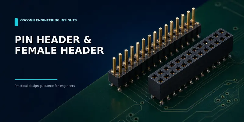
Pin Header and Female Header Connectors: A Complete Design Guide
Pin headers and female headers are among the simplest PCB interconnects, but small specification differences can determine whether the final assembly fits, carries the required current and survives repeated service.
This guide explains the parameters that belong on a drawing or RFQ: pitch, circuit count, row arrangement, orientation, pin dimensions, insulator height, mating depth, plating, current derating and packaging.
In brief: A “2.54 mm dual-row header” is not a complete specification. You still need position count, pin size, tail length, mating length, insulator height, orientation, plating zone, housing material, temperature rating and packaging.
Quick reference
| Pitch | Typical positioning | Common use | Design note |
|---|---|---|---|
| 1.00 mm | Single/dual row | Compact modules and dense control boards | Tighter PCB and assembly tolerances |
| 1.27 mm | Single/dual row | Compact industrial electronics | More density than 2.54 mm |
| 2.00 mm | Single/dual row | Industrial controls and embedded systems | Balance of density and robustness |
| 2.54 mm | Single/multiple row | Prototypes, development boards, general-purpose PCB connections | Broad ecosystem and easy handling |
| 3.96–5.08 mm | Usually single row | Larger power spacing or legacy equipment | Use product derating data for current |
These are common patterns, not guaranteed ratings for every series.
1. What are pin headers and female headers?
A pin header contains male contacts retained in an insulating strip. A female header—also called a socket or receptacle—contains spring contacts that accept the male pins.
The pair can connect:
- Two parallel PCBs
- A PCB to a removable module
- A PCB to a jumper or cable socket
- A development board to a shield or daughter card
- Test and programming equipment to a target board
“Breakaway” headers are manufactured in longer strips and separated into shorter lengths. This is convenient for prototypes, but production designs should still define the finished position count and inspect the cut end.
2. Specify the full contact geometry
For a straight through-hole male header, the critical dimensions typically include:
| Dimension | Why it matters |
|---|---|
| Pitch | Controls footprint and mating compatibility |
| Pin cross-section | Must match the female contact acceptance range |
| Mating length | Determines engagement and wipe |
| Tail length | Affects soldering process and board thickness |
| Insulator height | Contributes to board spacing and stability |
| Overall pin length | Determines protrusion and enclosure clearance |
| True position/coplanarity | Influences automatic assembly and mating |
For a female header, add entry style, mating depth, contact design and body height. Two connectors can share the same pitch while being mechanically incompatible because the male pin is too short, too large or outside the socket’s acceptable range.
3. Choose the row count and orientation
| Configuration | Advantages | Watch-outs |
|---|---|---|
| Single row | Narrow footprint, easy routing | Lower circuit density and less lateral stability |
| Dual row | Higher density and common mating ecosystem | Harder inner-row solder inspection |
| Three or more rows | Very high circuit count | More insertion force and less common sourcing |
| Straight/vertical | Best for parallel stacking or top-entry mating | Requires vertical clearance |
| Right-angle | Routes connection from PCB edge | Tail geometry and coplanarity are critical |
| Long/stacking pin | Enables board stacking or pass-through connection | Stack-height tolerance must be analyzed |
If reverse mating would damage the system, use a keyed housing or shrouded header rather than relying only on a pin-1 mark.
4. Define stack height correctly
For stacked boards, the required distance is usually the PCB-to-PCB spacing after mating. It depends on both connector halves, not the body height of one part.
Check:
- Nominal mated height
- Allowed variation across plug and receptacle
- PCB thickness tolerance
- Component keep-outs on both boards
- Standoff or screw height
- Board bow after reflow
- Minimum contact engagement at worst-case separation
A long-pin header provides flexibility, but a dedicated mezzanine connector is generally better when height precision, density or high-speed performance is critical.
5. Plating: specify the system, not just “gold”
Connector finishes normally include a base contact alloy, a nickel underplate and a final contact finish. Gold may be applied only to the mating area, with tin on the solder tail to control cost.
| Application | Common starting point | Engineering consideration |
|---|---|---|
| One-time or rarely serviced connection | Tin or selective precious-metal finish | Fretting and oxide behavior |
| Occasional maintenance | Gold over nickel in the mating zone | Required cycles and environment |
| Test fixture or frequent service | Heavier precious-metal finish or replaceable wear part | Mating force, lubrication and cost |
| Harsh humidity/contamination | Qualified finish system | Porosity, underplate and sealing |
Do not infer durability from color or a generic gold-thickness statement. Cycle life depends on contact geometry, normal force, lubricant, surface finish and the qualification method as well as plating.
6. Current rating and derating
The current capacity of a mated header is usually limited by the highest-resistance point and the allowed temperature rise. Important variables include:
- Male and female contact geometry
- Initial and aged contact resistance
- Number of adjacent loaded contacts
- Ambient temperature and airflow
- PCB copper connected to the tails
- Housing temperature rating
- Duty cycle and peak duration
The safe workflow is to obtain a current-versus-temperature derating curve for the exact mated pair and position count. If the load is shared across parallel contacts, distribute power and return pins so heat and current are not concentrated at one end of the connector.
For high-current rails, a dedicated power connector may provide better current sharing, lower resistance and more reliable touch protection than a large bank of signal contacts.
7. Housing material and soldering process
Through-hole headers may use cost-effective resin grades because the housing is not necessarily exposed to the full SMT reflow profile. SMT versions require a resin grade qualified for the specified lead-free profile, moisture handling and dimensional stability.
Ask for:
- Polymer family and exact grade
- UL 94 rating at the relevant thickness and color
- Maximum process/reflow conditions
- Long-term temperature rating
- Moisture handling instructions
- RoHS and REACH documentation
Avoid using polymer melting point as a direct proxy for service temperature.
8. Mating, retention and serviceability
Pin headers typically rely on socket contact force unless a latch, clip or surrounding housing is added. For field service or vibration:
- Add polarization or keying
- Consider a shrouded/latching system
- Support the PCB so unmating force does not flex it
- Define the permitted pull direction
- Avoid side-loading long pins
- Confirm durability after environmental conditioning
If a connection is only intended for factory programming, a pogo-pin fixture or edge test pad may eliminate unnecessary field-accessible contacts.
9. Drawing and RFQ checklist
Provide:
- Pitch, rows and total positions
- Straight, right-angle or stacking orientation
- Male/female mating pair
- Pin cross-section and acceptance range
- Tail, mating and insulator dimensions
- Target PCB-to-PCB spacing
- Through-hole or SMT termination
- Plating on contact zone and solder tail
- Continuous/peak current and loaded-contact count
- Voltage, temperature and environment
- Required mating cycles
- Housing color and material requirements
- Packaging: tube, tray, tape-and-reel or bulk
- Annual quantity and sample timing
FAQ
Is every 2.54 mm header compatible?
No. Pitch alone does not guarantee compatibility. Verify pin size, row spacing, mating length, socket entry, polarization and height.
Can a 2.54 mm header carry 3 A per pin?
Some products may be rated near that level under specific test conditions, but the mated socket, adjacent loaded contacts, ambient temperature and PCB copper determine the usable value. Use the exact series derating curve.
What is the difference between a female header and an IDC socket?
A female header is usually soldered to a PCB. An IDC socket terminates conductors in ribbon cable and often mates with a box header. Their contact arrangements can look similar but serve different assembly methods.
When should I replace a pin header with a mezzanine connector?
Consider a mezzanine connector when you need fine pitch, a precisely controlled low stack height, high pin count, characterized high-speed performance or improved mating guidance.
Request a matched header pair
Send GSConn the pitch, row/position count, orientation, stack height, current, mating-cycle target, plating requirement and annual volume. A matched plug-and-socket proposal should include both drawings so pin engagement and overall stack height can be checked together.
Sources and further reading
- https://webstore.iec.ch/en/publication/2365
- https://webstore.iec.ch/en/publication/2410
- https://www.te.com/content/dam/te-com/documents/industrial-intelligent-buildings/global/Connectors%20101_What%20Lighting%20Designers%20Need%20to%20Know_0217.pdf
- https://www.ul.com/services/plastics-testing-and-certification
Related guides: b2b-pin-header-current-rating.md · b2b-box-header-vs-pin-header.md · b2b-connector-selection-guide.md
Related reading on GSConn
- Wire-to-Board vs Board-to-Board Connectors
- Industrial USB Connector Guide
- IP67 vs IP68 USB Connector
- Stacked USB Connector Guide
- Request a Quote
Engineering references
- Product drawing, datasheet, material declaration and qualification report for the selected connector series
- IPC land-pattern and acceptability guidance applicable to the PCB assembly class
- Project-specific vibration, shock, thermal and electrical requirements