
Terminal Block Wire Size Guide: AWG, mm² and Ferrules
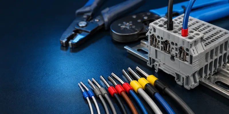
Correct wire fit is about more than matching an AWG number to a nominal mm² value. Engineers must check conductor class, strand construction, ferrule dimensions, strip length, number of conductors per clamping unit and the exact range covered by the terminal’s approval. This guide provides a practical starting point while keeping the final decision tied to the selected product datasheet.
Quick Reference: Approximate AWG to mm²
AWG and metric conductor sizes are different systems, so the values below are approximate comparisons rather than exact substitutions. The current column is a rough screening range only; allowable ampacity is governed by the wiring method, insulation temperature, ambient conditions and applicable code.
| AWG | mm² | Max Current (Copper, 30°C) | Typical Terminal Pitch |
|---|---|---|---|
| 26 | 0.14 | 2.2A | 3.5mm |
| 24 | 0.20 | 3.5A | 3.5mm |
| 22 | 0.34 | 5A | 3.5, 5.0mm |
| 20 | 0.50 | 7A | 3.5, 5.0mm |
| 18 | 0.75 | 10A | 5.0, 5.08mm |
| 16 | 1.5 | 15A | 5.08, 7.5mm |
| 14 | 2.5 | 20A | 5.08, 7.5, 7.62mm |
| 12 | 4.0 | 25A | 7.5, 7.62, 10.16mm |
| 10 | 6.0 | 35A | 10.16mm |
| 8 | 10.0 | 50A | Screw terminal >10mm² |
1. Ferrules: When They Help and When They Are Required
A wire ferrule, also called a cord-end terminal or bootlace ferrule, is a thin metal sleeve crimped onto a stranded conductor before insertion. Ferrules reduce strand splaying and can make production wiring more repeatable. They are not universally mandatory: many certified terminals accept flexible conductors without ferrules. Use a ferrule when the terminal instructions require or permit it and when the ferrule combination is covered by the intended approval.
Without Ferrule
Stranded wire → strands splay during insertion → some strands outside clamp → reduced contact area → hotspotWith Ferrule
Stranded wire → ferrule crimped on → solid cylindrical profile → clean insertion → all strands clamped → full contact areaFerrule Standards
| Standard | Color Code | Sizes |
|---|---|---|
| DIN 46228 Part 1 | French blue, gray, black, etc. | 0.14–10mm² |
| DIN 46228 Part 4 | Same colors, with plastic collar | 0.14–50mm² |
| UL listed ferrules | No color code | Per UL 486A |
Several ferrule color systems are used internationally, and the same color can represent different conductor sizes. Treat color as a production aid only; verify the printed size, packaging and crimp-tool setting.
Ferrule Selection Checklist
- Match the metal sleeve to the conductor cross-section and strand class.
- Check that the crimped ferrule falls within the terminal’s ferruled-conductor range.
- Use the specified strip length so the conductor reaches the full sleeve length.
- Use a controlled-cycle crimp tool and the profile recommended by the ferrule supplier.
- Do not tin stranded wire before clamping; solder can creep under pressure and reduce contact force.
2. Wire Strip Length
Strip length is determined by the terminal’s clamping geometry, not pitch alone. The values below are typical screening ranges; use the strip-length marking or datasheet for the exact product.
| Terminal Pitch | Strip Length | Too Short | Too Long |
|---|---|---|---|
| 3.5mm | 5–6mm | Wire not clamped | Exposed conductor — shock hazard |
| 5.0mm | 6–7mm | Poor contact | Exposed >1mm — fails inspection |
| 5.08mm | 7–8mm | Incomplete insertion | Safety violation |
| 7.5mm | 8–9mm | — | — |
| 7.62mm | 9–10mm | — | — |
| 10.16mm | 10–12mm | — | — |
No exposed conductor should be visible outside the terminal housing. If copper is visible, re-strip shorter or use a ferrule with an insulating collar.
3. Solid vs Stranded Wire in Terminals
| Solid Wire | Stranded Wire | Stranded + Ferrule | |
|---|---|---|---|
| Push-in terminal | ✅ Direct push | ❌ Must use tool or ferrule | ✅ |
| Spring clamp | ✅ | ⚠️ Ferrule recommended | ✅ Best |
| Screw terminal | ✅ | ⚠️ Ferrule recommended | ✅ Best |
| Reusability | Good | Poor (strands deform) | Excellent |
| Vibration | ⚠️ Can fracture | Better (flexible) | Best (gas-tight) |
Many spring and push-in designs accept flexible conductors directly when the actuator is used. Ferrules are often recommended for fast, repeatable insertion, especially with fine strands, but the terminal instructions determine whether they are optional, required or not permitted.
4. Twin Wire Entry (Two Wires per Terminal)
Some terminals accept two wires in one clamping point:
| Terminal | Twin Wire Capacity | Ferrule Required? |
|---|---|---|
| Screw, 2.5mm² | 2 × 0.5–1.5mm² | Recommended |
| Spring clamp, 2.5mm² | 2 × 0.5–1.0mm² | Required (one ferrule per wire) |
| Push-in, 2.5mm² | 2 × 0.5–0.75mm² | Required |
Twin entry halves the number of terminals needed. Common in PLC wiring (sensor 1 + sensor 2 share a common ground terminal).
Only place two conductors in one clamping unit when that configuration is explicitly approved. Some products accept unequal conductors or twin ferrules; others accept one conductor only. Never assume twin-wire capability from the opening size.
5. How to Specify the Connection Correctly
Record the complete combination on the drawing or work instruction:
- Terminal block manufacturer and exact part number.
- Conductor standard, material, cross-section/AWG and strand class.
- Bare, ferruled or other approved preparation.
- Ferrule part number and crimp tool where applicable.
- Strip length and insertion inspection criteria.
- Screw torque or actuator method.
- Number of conductors allowed per clamping unit.
Common Questions
Is 14 AWG exactly the same as 2.5mm²?
No. They are close in cross-sectional area but belong to different sizing systems and may have different outside diameters and strand constructions. Select a terminal approved for the actual conductor designation.
Can I put two wires under one screw?
Only when the product data explicitly lists two-conductor use for those sizes and conductor types. Otherwise, use a distribution terminal, jumper or approved twin ferrule arrangement.
Should stranded wire be solder-tinned before insertion?
Generally no. Under sustained clamp pressure, solder can creep and relax the connection. Use the bare flexible conductor or an approved ferrule as specified by the terminal manufacturer.
Match the Terminal to Your Conductor
GSConn terminal families cover a broad range of conductor sizes and connection technologies. Provide the conductor standard, AWG/mm², strand class, ferrule preference, current and approval market to receive a compatible series recommendation and wiring specification.
Related reading: