
Terminal Block Current Rating: Derating and Thermal Design
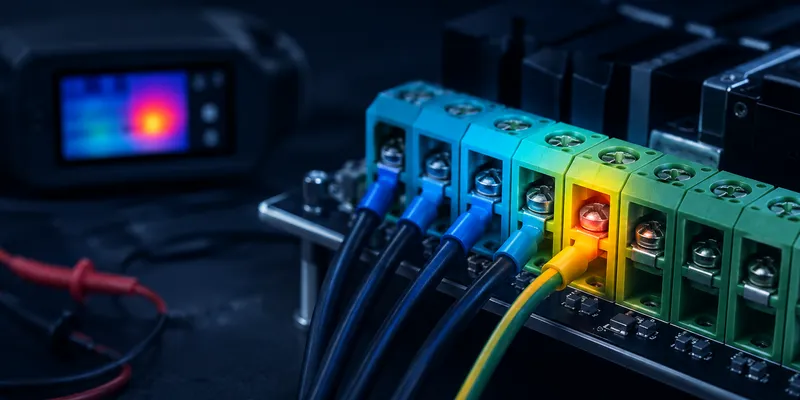
A terminal block’s nameplate current is a qualification result, not a universal operating limit. The usable current in a finished product depends on the exact part number, conductor type and size, number of loaded poles, ambient temperature, enclosure ventilation, PCB copper, installation method and applicable approval. This guide shows engineers how to move from a catalog rating to a defensible application current.
Typical Ranges at 25°C Ambient
The figures below are useful for early screening only. They are not interchangeable across suppliers or product series; always use the rating table and derating curve for the selected part.
| Pitch | Cross-Section (mm²) | IEC Current | UL Current | Max Wire |
|---|---|---|---|---|
| 3.5mm | 1.5 | 8A | 8A | 1.5mm² (16 AWG) |
| 5.0mm | 2.5 | 12A | 10A | 2.5mm² (14 AWG) |
| 5.08mm | 2.5 | 16A | 15A | 2.5mm² (14 AWG) |
| 7.5mm | 4.0 | 20A | 20A | 4mm² (12 AWG) |
| 7.62mm | 4.0 | 24A | 20A | 4mm² (12 AWG) |
| 10.16mm | 6.0 | 32A | 30A | 6mm² (10 AWG) |
| DIN Rail 2.5mm² | 2.5 | 24A | 20A | 2.5mm² |
| DIN Rail 6mm² | 6.0 | 41A | 30A | 6mm² |
1. Why IEC and UL Ratings Can Differ
IEC 60947-7-1 and UL 1059 rate terminals differently:
| Factor | IEC 60947-7-1 | UL 1059 |
|---|---|---|
| Qualification basis | Product-standard tests and declared ratings | Construction, conductor and temperature-rise tests under the certification conditions |
| Temperature limits | Limits are defined by the applicable product standard and material system | Limits depend on the certified use conditions and insulation system |
| Grouped installation | Use the manufacturer’s loaded-pole derating data | Use the certified rating and manufacturer application data; do not assume a universal factor |
| Wire size | Specified cross-section required | Specified AWG required |
The IEC and UL values printed for one terminal may differ because the test setup, conductor designation and certification conditions differ. Do not convert one rating into the other with a fixed percentage. For equipment sold into multiple regions, design to the rating applicable to each approval and verify the limiting case.
2. Temperature Derating
The following calculation is an example of how a supplier curve may be used; the factors are illustrative, not values prescribed for every terminal block.
| Ambient Temperature | Derating Factor | 16A Rated Terminal → | 24A Rated Terminal → |
|---|---|---|---|
| 25°C | 1.00 | 16A | 24A |
| 40°C | 0.90 | 14.4A | 21.6A |
| 55°C | 0.78 | 12.5A | 18.7A |
| 70°C | 0.63 | 10.1A | 15.1A |
| 85°C | 0.46 | 7.4A | 11.0A |
Current must be reduced when the combined ambient and self-heating approaches the temperature limit of the housing, contacts, plating or connected conductor. At high ambient temperature, the allowable current may fall sharply. Use the supplier’s curve for the exact pole count and conductor size.
3. Loaded-Position and Grouping Effects
When multiple terminals are mounted adjacent to each other, heat accumulates:
| Terminals Grouped | Derating Factor | 16A → | 24A → |
|---|---|---|---|
| 1 (isolated) | 1.00 | 16A | 24A |
| 2–3 grouped | 0.90 | 14.4A | 21.6A |
| 4–6 grouped | 0.80 | 12.8A | 19.2A |
| 7–10 grouped | 0.70 | 11.2A | 16.8A |
| Example conservative design factor | 0.80 | 12.8A | 19.2A |
Adjacent loaded poles share heat, so a long connector may carry less current per pole than a two-position sample. A factor such as 0.80 is sometimes used as a conservative early estimate, but it is not a substitute for the product’s certification data or manufacturer derating curve.
4. Wire Size vs Current
Using undersized wire limits the terminal’s effective current rating:
| Terminal Rated | Wire Connected | Actual Usable Current | Why |
|---|---|---|---|
| 24A (4mm²) | 1.5mm² | 16A (limited by wire) | Wire heats up before terminal |
| 16A (2.5mm²) | 4mm² | 16A (limited by terminal) | Terminal is the bottleneck |
| 16A (2.5mm²) | 2.5mm² | 16A | Matched — optimal |
5. Short-Circuit Coordination
Terminal blocks must survive short-circuit currents without welding contacts or disintegrating:
| Example Design Class | Illustrative Withstand Target | Protection Needed |
|---|---|---|
| ≤16A | 1.5 kA | Yes (matching class) |
| ≤32A | 3 kA | Yes |
| ≤63A | 6 kA | Yes |
| >63A | 10 kA | Yes |
Short-circuit performance is system-specific. The available fault current, overcurrent protective device, conductor and terminal block must be coordinated using the equipment standard and the terminal’s certified conditions of acceptability. Never assign an SCCR from terminal pitch or continuous-current rating alone.
6. A Practical Current-Rating Workflow
- Define the continuous current, duty cycle, ambient range and maximum enclosure temperature.
- Select a terminal that accepts the required conductor type and cross-section.
- Check the exact IEC, UL or other approval rating required for the destination market.
- Apply the manufacturer’s derating curve for loaded positions and ambient temperature.
- Include PCB trace, copper area, connector contact resistance and enclosure airflow in the thermal model.
- Validate the worst-case build with temperature-rise testing at the intended conductor preparation and tightening torque.
- Coordinate the terminal with the upstream fuse or circuit breaker and document the result.
Common Questions
Can I use the catalog current at 60°C ambient?
Only if the exact datasheet permits it for your conductor size and number of loaded poles. Otherwise, apply the published derating curve or obtain written application guidance.
Does a larger wire automatically increase terminal current capacity?
Not beyond the terminal’s approved rating. A larger conductor may reduce wire heating, but the clamp, current bar, PCB pins and insulation remain limiting elements.
What should I measure during validation?
Measure temperature rise at the current path and nearby housing under stabilized worst-case conditions. Record ambient temperature, conductor size and preparation, loaded positions, torque, enclosure state and protective device.
Need Help Confirming the Application Current?
GSConn can provide series-specific ratings, derating curves, conductor conditions and temperature-rise data where available. Send the target current, ambient temperature, pole count, wire size, PCB copper information and required market approvals for an application review.
Related reading: