
How to Select a Terminal Block: Engineer’s Guide
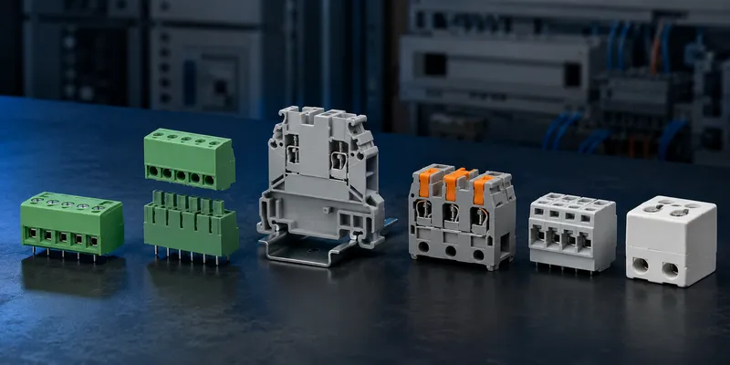
The right terminal block must satisfy electrical, mechanical, environmental and certification requirements at the same time. Start with the circuit and conductor—not with pitch or price—then narrow the choice by mounting, connection technology, service needs and target market. This guide provides a repeatable selection process for PCB, DIN-rail and high-temperature applications.
Quick Decision Matrix
Current ranges are typical screening values only. Exact ratings depend on the selected series, conductor, loaded positions, ambient temperature and approval.
| If you need… | Choose This Type | Typical Current | Best For |
|---|---|---|---|
| Low-cost, permanent wiring | Screw Terminal | 10–76A | Industrial panels, power distribution |
| Fast wiring, vibration-proof | Spring Clamp (Cage Clamp) | 10–40A | Railway, machinery, automation |
| Tool-free, high-speed assembly | Push-in Terminal | 10–24A | Production line, frequent rewire |
| Modular, removable connection | Pluggable Terminal | 8–16A | Field service, modular equipment |
| DIN rail mounting | DIN Rail Terminal | 10–100A | Control cabinets, PLC wiring |
| PCB-mounted, compact | PCB Terminal (Screw or Spring) | 5–16A | PCB-to-wire on circuit boards |
| Feed-through (wire-to-wire) | Feed-Through Terminal | 10–100A | Junction boxes, distribution |
| High temperature (>150°C) | Ceramic Terminal | 10–50A | Heating elements, ovens, furnaces |
1. Five Terminal Block Families
Screw Terminal (Most Common)
A metal clamping cage tightened by a screw. The wire is inserted and the screw torques down to clamp the wire against the current bar.
| Parameter | Specification |
|---|---|
| Wire range | 0.14–50mm² (26–1/0 AWG) |
| Current | 10–76A (standard), up to 150A (power) |
| Torque | 0.5–1.2 N·m (typical) |
| Reusability | High — wire can be removed and reinserted many times |
| Cost | Lowest |
| Maintenance | Follow the manufacturer and equipment maintenance instructions; use controlled torque during assembly |
When to use: Industrial panels, power distribution, any application where cost and familiarity matter. Screw terminals are the default in electrical engineering.
Spring Clamp (Cage Clamp)
A spring-loaded clamp holds the wire against the current bar. No screw — the spring provides constant clamping force.
| Parameter | Specification |
|---|---|
| Wire range | 0.08–35mm² |
| Current | 10–40A |
| Tool | Screwdriver to open spring (standard flathead) |
| Vibration performance | Constant spring force; verify shock and vibration qualification for the exact product |
| Contact stability | Spring follows conductor settlement and maintains defined force |
| Cost | 1.5–2× screw terminal |
When to use: Railway, machinery, wind turbines, any application with vibration or where maintenance-free connections are required.
See Screw vs Spring vs Push-in.
Push-in Terminal (Tool-Free)
Wire is pushed directly into the terminal — spring clamp engages automatically. No tool needed for solid conductors; screwdriver release for stranded/flexible wires.
| Parameter | Specification |
|---|---|
| Wire range | 0.14–4mm² (solid), 0.14–2.5mm² (stranded with ferrule) |
| Current | 10–24A |
| Tool | None for solid wire. Screwdriver to release |
| Speed | Usually the fastest for compatible rigid or ferruled conductors; validate with a production trial |
| Cost | 2× screw terminal |
When to use: High-volume production, control panels with hundreds of terminations, applications where wiring speed directly affects cost.
Pluggable Terminal
Two-piece design: a base (PCB-mount or DIN rail) and a plug (wire connection side). The plug can be disconnected without disturbing the wiring.
| Parameter | Specification |
|---|---|
| Pitch | 3.5, 5.0, 5.08, 7.5, 10.16mm |
| Current | 8–16A |
| Mating cycles | Series-specific; commonly tens to hundreds |
| Key feature | Disconnect without removing wires |
When to use: Modular equipment, field-replaceable units, test fixtures. Technicians unplug the terminal block instead of unscrewing each wire.
See Pluggable Terminal Block Guide.
PCB Terminal (Board-Mount)
Screw or spring terminal soldered directly to a PCB. Common in power supplies, motor drives, and industrial controllers.
| Parameter | Specification |
|---|---|
| Pitch | 3.5, 5.0, 5.08, 7.62mm |
| Orientation | Horizontal, vertical, 45° |
| Current | 5–16A |
| Mounting | Through-hole (standard), SMT available |
2. Key Selection Parameters
| Parameter | What to Check |
|---|---|
| Wire size (AWG / mm²) | Check solid, stranded and ferruled ranges separately; AWG and mm² are not exact equivalents. |
| Current rating | Use the exact rating and derating curve for conductor size, loaded poles, ambient and approval. |
| Voltage rating | Use the certified value for the exact product and installation; pitch alone does not establish voltage. |
| Pitch (PCB terminals) | 3.5–10.16mm. Smaller pitch = more positions per PCB length. |
| Number of positions | 1–24 standard. Linkable (stackable) terminals for any count. |
| Mounting | PCB (TH/SMT), DIN rail (EN 50022), panel screw, or snap-in |
| Wire entry | Top, side, angled, or dual entry (top + side) |
| Housing material | Check the specific polymer grade, temperature index, flammability and chemical resistance; use ceramic where the application requires it. |
| Flammability | Match the material and product certification to the end-product requirement. |
| Certification | UL 1059 (US/Canada), IEC 60947-7-1 (international), CSA |
3. DIN Rail Terminal System
DIN rail terminals (EN 50022, 35mm rail) are the backbone of industrial control cabinets. Terminals snap onto the rail and can be connected via jumper bars:
[DIN Rail - 35mm]
  ├── Terminal 1 (Feed-through, 2.5mm²)
  ├── Terminal 2 (Feed-through, 2.5mm²)  ── Jumper bar connects 1-2-3
  ├── Terminal 3 (Feed-through, 2.5mm²)
  ├── Terminal 4 (Ground, green-yellow)
  ├── Terminal 5 (Fuse terminal, 5×20mm)
  ├── Terminal 6 (Disconnect / knife switch)
  └── End plate + end bracket
DIN Rail Terminal Types
| Type | Function |
|---|---|
| Feed-through | Straight wire-to-wire connection |
| Ground (PE) | Green-yellow, connects to DIN rail for earth |
| Fuse | Holds 5×20mm or 6.3×32mm fuse |
| Disconnect | Knife switch to isolate circuit without removing wires |
| Double-deck | Two independent circuits in one terminal width |
| Sensor / actuator | Three-level (power + signal + ground) |
4. Seven-Step Selection Process
- Define circuit current, voltage, duty cycle, fault level and required protection.
- Define the conductor: material, solid/stranded class, AWG/mm², insulation diameter and ferrule use.
- Choose the mounting system: PCB, DIN rail, panel or free-hanging junction.
- Choose the connection technology based on production rate, vibration, access and service strategy.
- Check geometry: pitch, positions, wire-entry direction, bend radius, touch safety and tool clearance.
- Check environment: ambient temperature, heat sources, vibration, contamination, condensation and chemicals.
- Verify the exact approval, rating conditions, accessories and installation instructions before release.
5. Common Selection Mistakes
- Selecting by pitch while ignoring conductor and loaded-pole derating.
- Treating a typical catalog table as the rating for every pole count.
- Mixing plugs and headers because they share the same nominal pitch.
- Using a ferrule or twin-wire arrangement not covered by the terminal instructions.
- Forgetting jumper current, PCB copper capacity or enclosure temperature.
- Assuming a certification logo alone proves suitability for the end product.
- Leaving too little space for labels, wire bend radius, test probes or screwdrivers.
6. GSConn Terminal Block Portfolio
| Series | Type | Pitch | Current | Features |
|---|---|---|---|---|
| TB-SC-508 | Screw, PCB | 5.08mm | 16A | Standard industrial PCB screw |
| TB-SP-508 | Spring, PCB | 5.08mm | 12A | Vibration-proof, tool-less wire entry |
| TB-PL-508 | Pluggable, PCB | 5.08mm | 12A | 2-piece removable, 200 cycles |
| TB-DR-25 | DIN Rail, 2.5mm² | N/A | 24A | Feed-through, gray, UL/IEC |
| TB-DR-GND | DIN Rail, ground | N/A | N/A | Green-yellow, PE terminal |
| TB-CER | Ceramic, screw | N/A | 30A | 250°C continuous, heating elements |
Request a Series Recommendation
GSConn terminal families include PCB screw and spring types, pluggable connectors, DIN-rail feed-through and PE terminals, and high-temperature ceramic options. Send the circuit data, conductor specification, environment, layout constraints and destination markets to receive a shortlist with datasheet-confirmed ratings.
Related reading: