
Terminal Blocks for Industrial Control Cabinets
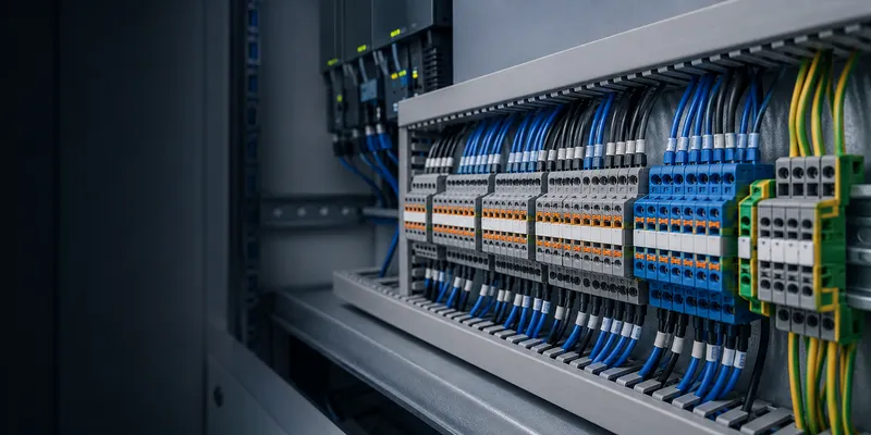
Terminal blocks are the organized interface between field wiring and the devices inside an industrial control cabinet. A good terminal plan improves assembly speed, test access, fault isolation and future expansion. A poor plan creates crowded wiring ducts, ambiguous labels and avoidable service risk. This guide explains how to build a practical terminal architecture for PLC, sensor, motor and power circuits.
Application Quick Reference
The ranges below are typical starting points. Final conductor size, current and approvals must match the selected terminal and the end-product design.
| Application | Terminal Type | Typical Wire Size | Features Needed |
|---|---|---|---|
| PLC I/O wiring | Spring clamp, 2.5mm² | 0.5–1.5mm² | High density, labeling, jumper bars |
| Motor power (3-phase) | Screw terminal, 6–16mm² | 2.5–10mm² | High current, clear marking |
| Analog signal (0–10V, 4–20mA) | Spring or screw, 2.5mm² | 0.5–1.5mm² | Shield connection, fine-wire suitable |
| Ground / PE (protective earth) | Screw, green-yellow, 4–16mm² | 2.5–16mm² | Direct DIN rail contact, UL listed for ground |
| Sensor / actuator (3-wire) | 3-level terminal, 2.5mm² | 0.5–1.5mm² | Power + signal + ground in one width |
| Power distribution | Screw, 10–35mm² | 4–25mm² | Bus bar, high current, UL 1059 |
1. The Industrial Control Cabinet: Terminal Block Architecture
A typical PLC control cabinet has this terminal layout:
[Field Devices]  ←wire→  [DIN Rail Terminal Strips]  ←wire→  [PLC I/O Modules]
                               │
                         Jumper bars
                         (common power, ground)
                               │
                         [DIN Rail Power Distribution]
                         (24V DC, 0V, PE)
Terminal blocks serve three roles:
- Interface: Connect field wiring (sensors, actuators, motors) to cabinet wiring
- Distribution: Share power and ground across multiple circuits via jumper bars
- Protection: Fuse terminals protect individual circuits; disconnect terminals isolate for maintenance
2. DIN Rail Terminal Types for Industrial Control
Feed-Through (Most Common)
Simple wire-to-wire connection. One wire in, one wire out. Available in gray (signal), blue (DC neutral / 0V), and red (DC positive).
| Wire Size | Width | Current | Use |
|---|---|---|---|
| 2.5mm² | 5.2mm | 24A | General signal, PLC I/O |
| 4mm² | 6.2mm | 32A | Power distribution |
| 6mm² | 8.2mm | 41A | Motor power |
| 10mm² | 10.2mm | 57A | Main power feed |
| 16mm² | 12mm | 76A | Main disconnect |
Ground / PE Terminal (Green-Yellow)
Connects to the DIN rail itself. The terminal’s foot has a metal contact that touches the rail. All PE terminals on the same rail are electrically connected through the rail.
Critical: Use PE terminals and rail-bonding components that are approved for the intended protective-conductor function. Follow the panel standard and the terminal manufacturer’s instructions for rail material, mounting, conductor size and bonding continuity.
Fuse Terminal
Holds a 5×20mm or 6.3×32mm cartridge fuse. Protects individual circuits without needing a separate fuse holder:
| Fuse Size | Terminal Width | Voltage | Fuse Types |
|---|---|---|---|
| 5×20mm | 6–8mm | 250V | Glass, ceramic, time-delay |
| 6.3×32mm | 8–10mm | 600V | Class CC, midget |
Disconnect / Knife Switch Terminal
A built-in disconnect element opens the circuit without removing wires. It is useful for testing and functional isolation. Do not treat a disconnect terminal as a safe-isolation device unless the product and installation are explicitly rated for that function. Apply the required lockout/tagout and absence-of-voltage procedure before maintenance.
Multi-Level Terminal
Two or three independent circuits in one terminal width. Saves 50–66% DIN rail space.
| Levels | Terminal Width | Circuits | Use |
|---|---|---|---|
| Double-deck | 5–6mm | 2 | Two signals in one width |
| Three-level | 5–6mm | 3 | Sensor: +24V / signal / 0V |
| Four-level | 6–8mm | 4 | High density, rare |
3. Jumper Bars: Sharing Across Terminals
Jumper bars (also called comb bars or cross-connection bars) link adjacent terminals to share power, ground, or common signals:
| Jumper Type | Positions | Current | Use |
|---|---|---|---|
| 2-way | 2 | 24A | Short jump |
| 10-way | 10 | 24A | Common 24V bus |
| 50-way | 50 | 24A | Full-row distribution |
| Insulated | 2–50 | 24A | Standard (fingers insulated from each other) |
| Continuous | 2–50 | 24A | All positions connected (no breaks) |
4. Control Cabinet Best Practices
| Practice | Why |
|---|---|
| Separate power and sensitive signal wiring | Reduce coupling according to the EMC plan; spacing and routing depend on voltage, current, cable type and enclosure layout |
| Prepare stranded conductors as specified | Use bare flexible conductors or approved ferrules according to the terminal instructions |
| Label every terminal | 5 seconds of labeling saves 5 minutes of troubleshooting |
| Leave 20% spare terminals | Future expansion without rewiring the cabinet |
| Terminate spare conductors safely | Insulate and identify unused conductors; bond only shields or conductors that the design explicitly requires |
| Torque screw terminals with a calibrated tool | Provides repeatable clamping force when the specified torque and conductor preparation are followed |
5. A Better Cabinet-Terminal Planning Workflow
- Group circuits by function: mains, motor power, 24V DC, safety, analog, digital I/O, communication, shields and PE.
- Estimate conductor count and add realistic spare capacity for future changes.
- Select connection technology based on wire type, vibration, assembly volume and maintenance strategy.
- Reserve test points and disconnect or fused functions where troubleshooting requires them.
- Size jumpers and distribution blocks for the total downstream current, not just one branch.
- Verify clearance to wire duct, bend radius, labels and tool access before freezing the rail layout.
- Check terminal ratings, accessories and PE functions against the required panel certification.
Common Questions
How much spare terminal capacity should a panel include?
Many projects reserve about 10–20%, but the right figure depends on expected expansion, cabinet space and customer specification. Spare positions should be labeled and included in the drawings.
When should I use multi-level terminals?
Use them when rail space is constrained and related potentials can be grouped clearly, such as 24V/signal/0V for three-wire sensors. Confirm visibility, marking and tool access remain acceptable.
Are fuse terminals a replacement for branch-circuit protection?
Not automatically. The fuse, holder, terminal and upstream protection must be coordinated for the circuit and end-product standard.
Build a Complete Terminal System
GSConn supplies feed-through, PE, fuse, disconnect and multi-level terminal families with matching jumpers, end plates, end brackets and marking accessories. Share the I/O list, conductor sizes, circuit currents, rail layout and target approvals for a series recommendation and bill-of-material review.
Related reading: