
Low-Profile Board-to-Board Connectors: Stack-Height Selection Guide
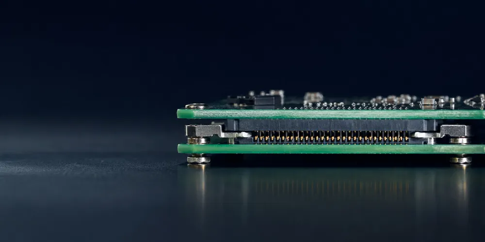
Low-profile board-to-board connectors reduce the vertical distance between PCBs and are central to thin consumer electronics, compact cameras, embedded modules, and space-constrained industrial products. The smallest possible connector is not always the best connector: a lower stack height can reduce routing and component clearance, mechanical tolerance, and serviceability.
Key Takeaways
- Define mated height, tolerance, and allowable compression as a controlled mechanical stack.
- Reserve the connector envelope, mating path, and component keep-outs in the 3D model before PCB release.
- Ultra-low stacks improve packaging density but can reduce probing, rework, airflow, and routing freedom.
- Choose the lowest height that still preserves alignment, signal integrity, manufacturability, and service life.
Quick Selection Guide
| Design Goal | Connector Direction | What to Prioritize |
|---|---|---|
| Minimum product thickness | Fine-pitch low-stack mezzanine | Mated height and component keep-out |
| More tolerance between boards | Floating mezzanine | X/Y float and board guidance |
| Frequent service | More robust mated height / retention | Durability and handling |
| High-speed compact module | Low-profile high-speed B2B | S-parameters and breakout geometry |
| Power-heavy interface | Hybrid or dedicated power connector | Temperature rise rather than minimum height |
1. Understand “Mated Height” Correctly
Mated height or stack height is the specified distance between the mating PCBs for a given plug/receptacle combination. It is not the same as the height of one connector half.
Before selecting a connector, define the vertical stack:
PCB thickness + bottom-side components + mated connector height + top-side components + enclosure clearances
The connector can become the controlling dimension, but in many designs the tallest nearby component—not the connector—sets the product thickness.
2. Real Low-Profile Examples
Molex SlimStack
Molex SlimStack includes ultra-fine-pitch board-to-board products with very low mated heights. The family spans many sub-series, so pitch, current, operating temperature, durability, and height should be checked using the exact part number.
Hirose DF40
Hirose DF40 is a 0.4 mm-pitch board-to-board/FPC-to-board family with published stacking-height options from 1.5 mm to 4.0 mm. It demonstrates a common trade-off in low-profile design: compact geometry must still provide alignment, contact protection, and usable mating length.
3. The Hidden Cost of Going Lower
Reducing stack height can affect several design margins.
| Area | Potential Effect |
|---|---|
| Component clearance | Less room between facing PCB components |
| Board flex | Stiffer mechanical stack can increase connector stress |
| Routing | Fine pitch can force smaller vias or denser breakout |
| Inspection | Very low gaps reduce visual access after assembly |
| Rework | Tool access becomes more difficult |
| Mating | Operators have less leverage and alignment visibility |
Therefore, set a maximum acceptable mated height, not simply “the lowest available connector.”
4. Alignment and Tolerance
Low-profile connectors often have limited engagement travel. The mechanical design should control:
- X/Y placement tolerance between boards;
- angular misalignment;
- standoff-height tolerance;
- board bow and twist;
- enclosure compression;
- insertion direction.
If those tolerances are difficult to hold, consider a floating connector or a connector with generous self-alignment guides rather than forcing a rigid ultra-low profile solution.
5. Component Keep-Out Between Stacked Boards
A 1.5 mm board-to-board stack does not provide 1.5 mm of usable component height everywhere. Connector housings, solder fillets, board flatness, shield cans, and tolerance require margin.
Create a 3D assembly model early and check:
- tallest components under the opposing PCB;
- test points and programming headers;
- connector insertion path;
- shielding and thermal pads;
- rework nozzle access;
- enclosure ribs or fasteners.
6. Electrical Performance
Low profile can be beneficial for high-speed signals because short contact paths reduce interconnect length, but the whole channel still matters. Evaluate:
- connector differential impedance behavior;
- insertion loss and return loss;
- crosstalk;
- PCB breakout vias;
- reference-plane transitions;
- ground allocation.
For high data rates, request or use manufacturer S-parameter models when available and simulate the actual stack height and pin assignment.
7. Reliability and Serviceability
For products that are assembled once in a controlled factory, ultra-low-profile connectors can be ideal. For equipment that is serviced repeatedly in the field, a slightly taller connector with better access, alignment, and mechanical protection may provide a lower lifecycle risk.
Consider:
- specified mating-cycle life;
- handling by operators;
- board removal angle;
- latch or hold-down features;
- connector visibility during mating;
- shock and vibration requirement.
8. Selection Workflow
- Define the maximum allowed PCB-to-PCB spacing.
- Add component and enclosure clearance requirements.
- Define circuit count, current, and high-speed interfaces.
- Compare actual plug/receptacle mating combinations.
- Build the tolerance stack in the mechanical CAD model.
- Validate footprint and assembly process with the PCB/EMS team.
- Prototype the complete stack—not just the connector pair.
GSCONN Selection Support
For a GSCONN low-profile board-to-board design, specify target mated height, PCB dimensions, circuit count, current, signal rate, operating environment, and assembly tolerances. Final dimensions and ratings should be taken from the applicable product drawing and datasheet.
FAQ
Is lower stack height always better?
No. Lower height can reduce mechanical and assembly margin. Choose the lowest height that still meets reliability, routing, and service requirements.
Are low-profile connectors only for phones and wearables?
No. They are also used in cameras, embedded computing, instrumentation, industrial modules, and any product with tight Z-height constraints.
Does a low-profile connector automatically support high speed?
No. High-speed capability depends on the contact system, pin field, stack height, PCB breakout, and full-channel design.
Related reading:
- High-Density Board-to-Board Connector Guide
- SMT Board-to-Board Connector Guide
- PCB Board-to-Board Connector Design Guide
Technical References
- Molex SlimStack connector portfolio
- Hirose DF40 series overview
- Hirose DF40/DF40T stacking-height overview
Related reading on GSConn
- Wire-to-Board vs Board-to-Board Connectors
- Industrial USB Connector Guide
- IP67 vs IP68 USB Connector
- Stacked USB Connector Guide
- Request a Quote
Engineering references
- Product drawing, datasheet, material declaration and qualification report for the selected connector series
- IPC land-pattern and acceptability guidance applicable to the PCB assembly class
- Project-specific vibration, shock, thermal and electrical requirements