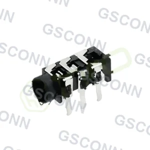
Audio Jack Detection Switches: Tip, Ring and Sleeve Configurations Explained

A switch is not a sensor until firmware reads it correctly
An audio jack with detection switches is sold as a part with “insertion detection.” Electrically, what you get is one or two spring blades that open or close when a plug arrives. Everything else — what the switch means, how to debounce it, what state machine follows — is the designer’s job.
This article covers the three switch positions on a typical jack, what each can and cannot tell you, the wiring topologies that extract plug-type information, and the firmware behaviour that avoids audible glitches.
The three switch positions
Switches are placed against specific contact fingers, and their position determines what they detect.
| Switch | Resting state (no plug) | State with plug | What it reports |
|---|---|---|---|
| Tip switch | Closed against the tip contact | Opens as the tip pushes the blade away | Any plug has been inserted |
| Ring switch | Closed against the ring contact | Opens when the ring conductor reaches the blade | Plug has reached the ring position |
| Sleeve switch | Closed against the sleeve contact | Depends on plug type — see below | Whether the sleeve is a ground conductor or a signal |
The sleeve switch is the interesting one, and it is the basis for distinguishing a three-pole plug from a four-pole plug.
How the sleeve switch tells plug types apart
A three-pole plug has one long sleeve conductor covering the whole back section. A four-pole plug splits that section into two separate conductors — ring 2 and sleeve — with an insulating band between them.
Wire the sleeve switch so that it is normally closed against the sleeve contact, and connect the mic contact such that the switch bridges it to the sleeve when no plug is present.
| Plug inserted | Sleeve switch state | What it means | Host action |
|---|---|---|---|
| None | Closed | No plug | Audio to speaker |
| TRS (3-pole) | Closed — the long sleeve bridges both contacts | Headphones, no microphone | Mute speaker, disable mic input |
| TRRS (4-pole) | Open — the insulating band separates the contacts | Headset with microphone | Mute speaker, enable mic input |
This is why a four-pole jack often has five or six contacts rather than four. The extra contacts are not signal paths; they are switch blades reading the plug geometry.
Note what this does not tell you: it says nothing about whether the headset is CTIA or OMTP wired. Resolving that requires bias-polarity detection at the codec, which is a separate mechanism.
Normally open versus normally closed
Both variants exist, and the difference is not cosmetic — it inverts your firmware logic.
| Type | No plug | Plug inserted | Firmware implication |
|---|---|---|---|
| Normally closed | Switch conducts | Switch opens | Pull-up reads low with no plug |
| Normally open | Switch open | Switch closes | Pull-up reads high with no plug |
Datasheets frequently list “with switch” without stating the resting state. Getting it wrong produces a product that appears to work during bring-up with a plug already inserted, then behaves backwards in the field.
Specify it explicitly: “tip switch normally closed, opens on insertion.” Do not accept a datasheet that omits it.
Reading the switches without glitches
The blades are light and undamped. They bounce on insertion and they chatter under vibration.
| Requirement | Typical value | What goes wrong if omitted |
|---|---|---|
| Debounce on insertion | 10–50 ms stable | Multiple edges start and restart the audio path |
| Debounce on removal | Longer, often 2–5× insertion | A momentary lift is treated as unplugging; audio pops |
| Hysteresis | Distinct thresholds per direction | Toggling when the blade sits near its threshold |
| Interrupt edge | Both edges, or poll at a fixed rate | Missed transitions if only one edge is configured |
| Pull-up or pull-down | Defined value, not floating | Noise pickup on a high-impedance input |
The asymmetric debounce is the item most often missed. Recognising insertion quickly makes the product feel responsive. Recognising removal quickly makes it pop and click every time vibration briefly lifts a blade.
A state machine that behaves
The switches give discrete states. The firmware should model them explicitly rather than reacting to individual edges.
| State | Tip switch | Sleeve switch | Meaning | Audio routing |
|---|---|---|---|---|
| Empty | Closed | Closed | No plug | Speaker, mic disabled |
| Inserting | Open | Closed | Plug in, not fully seated | Hold previous state |
| Headphones | Open | Closed, stable | 3-pole plug | Jack, mic disabled |
| Headset | Open | Open, stable | 4-pole plug | Jack, mic enabled |
| Removing | Closed | Any | Plug leaving | Wait for debounce, then to speaker |
The “inserting” state is the one worth having. It distinguishes a plug that is partway in from one that is fully seated, which prevents the host from enabling the microphone against a plug that is still moving.
Using an ADC instead of switches
Some designs read the mic line with an ADC rather than relying only on switches. That allows more information but also more complexity.
| Method | Information obtained | Cost |
|---|---|---|
| Switches only | Plug present, plug type (3 or 4 pole) | Two GPIOs |
| Switches plus impedance | Above, plus confirmation of a mic load | ADC channel or comparator |
| Switches plus bias polarity | Above, plus CTIA versus OMTP | Reversible bias supply, firmware |
| ADC on all four contacts | Fault detection, short detection | More channels, more firmware |
For most products the second row is the right level. The third is worth it if the product must work with any headset the customer brings.
Protection is part of the interface
Every contact on the jack is externally accessible. That makes each one an ESD entry point and a possible fault path.
| Contact | Protection needed | Why |
|---|---|---|
| Tip and ring (audio out) | Series resistance plus TVS | Protects the amplifier from a short to ground |
| Mic input | Series resistance, TVS, bias current limit | A shorted plug can draw the full bias current |
| Sleeve / ground | Direct connection, short path | Reference for all signals |
| Switch contacts | Series resistance into the GPIO | Limits fault current if a switch shorts to a signal line |
The microphone bias is the contact most often left unprotected. A plug inserted at an angle can momentarily short the mic contact to ground, and without a current limit that appears as a codec failure rather than a plug event.
FAQ
What does the sleeve switch detect? Whether the sleeve conductor is a single long ground (three-pole plug) or split into ring 2 and sleeve (four-pole plug), because the insulating band between them opens the switch.
Can the switches tell me if the headset is CTIA or OMTP? No. They report plug geometry only. Resolving the wiring standard needs bias-polarity detection at the codec.
Why does my jack have six contacts for four poles? The two extra are switch blades, not signal paths. They read plug presence and plug type.
How long should the debounce be? 10–50 ms for insertion, longer for removal. The asymmetry matters more than the exact value.
Is my switch normally open or closed? Check the drawing. Both exist, and getting it wrong inverts the logic in a way that looks correct during bench testing with a plug inserted.
Do I need an ADC on the mic line? Only if you need to confirm a microphone load or detect faults. Switches alone handle presence and plug type.
Audio Connectors for this design
View all 134 parts →