
Box Header vs Pin Header: When a Shrouded Connector Is Worth It
Box Header vs Pin Header: When a Shrouded Connector Is Worth It
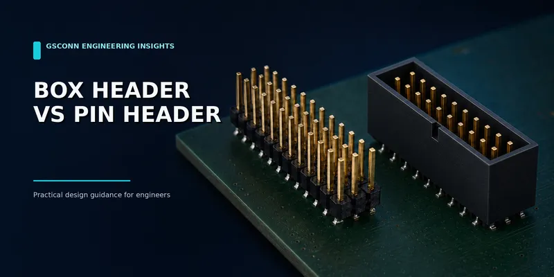
A box header is essentially a pin array surrounded by a molded shroud. That extra housing increases footprint and cost, but it can also protect contacts, guide mating, support polarization and provide a latch.
The right choice depends less on the electrical schematic than on how the product will be assembled and serviced.
Short answer: Choose an open pin header when space, cost and configuration flexibility dominate. Choose a box header when orientation control, pin protection, IDC compatibility or field-service reliability matters.
Quick comparison
| Feature | Open pin header | Box/shrouded header |
|---|---|---|
| Pin exposure | Exposed | Recessed within shroud |
| Mating guidance | Limited | Housing guides the mate |
| Polarization | Usually none unless separately keyed | Often built into shroud/socket system |
| Latching | Normally friction only | Friction, center latch or side latch options |
| IDC ribbon-cable use | May physically mate with some sockets, but lacks normal key/latch protection | Standard use case for many dual-row systems |
| Footprint | Smaller | Larger |
| Breakaway/custom length | Widely available | Normally fixed position counts |
| Probe access | Easy | More restricted |
| Best fit | Prototypes, debug, internal low-risk links | Production wiring, serviceable equipment, cable assemblies |
1. What the shroud changes
The shroud can perform four practical functions:
- Mating guidance. The socket housing aligns before the contacts fully engage.
- Pin protection. Recessed pins are less likely to be bent during handling.
- Polarization. A key or asymmetric geometry helps prevent an unintended orientation.
- Retention. Latch features can resist vibration or cable pull.
These benefits are especially valuable when a technician works in a crowded enclosure or when the cable is disconnected during maintenance.
Polarization should still be verified as a complete mating-system feature. A shroud alone is not proof that every incorrect mate is physically impossible; key location, missing-pin arrangements and mating socket geometry all matter.
2. IDC ribbon-cable applications
Many 2.54 mm and 2.00 mm dual-row box headers are designed to mate with insulation-displacement (IDC) ribbon-cable sockets. This creates a repeatable cable system:
- Conductors remain in a fixed order
- Pin 1 can be identified by cable stripe and connector key
- Strain-relief accessories can support the cable
- Latching versions resist accidental unplugging
- Cable assemblies can be electrically tested before installation
When specifying an IDC pair, match:
- Pitch and row spacing
- Position count
- Key position and polarization
- Header wall/latch geometry
- Cable conductor pitch and wire size
- Strain relief and pull direction
Do not assume that any dual-row socket will fit any header with the same pin grid.
3. Latching and retention
Retention is product-specific. A center latch may be easy to release with one hand, while dual side latches can provide stronger resistance to unintended unmating. Friction-only versions simplify packaging where vibration is low.
Evaluate:
| Requirement | Question |
|---|---|
| Cable pull | Can the cable load bypass the contacts through strain relief? |
| Vibration | Has the complete mated pair been tested in the intended direction? |
| Service access | Can the latch be reached without pulling wires? |
| PCB stress | Does unmating flex the board or solder joints? |
| Tool use | Is a release tool required, and can it damage nearby components? |
Avoid publishing a universal retention-force value for a latch type. Contact count, latch geometry, material and test direction all change the result.
4. When an open pin header is better
An open header remains the stronger choice when:
- The connection is inside a controlled assembly and is rarely disturbed
- The design needs a narrow footprint
- Engineers need direct probe or jumper access
- Multiple position counts are built from breakaway strips
- Breadboard or development-board compatibility is required
- A long or custom mating pin is needed for stacking
- Unit cost is highly constrained and reverse mating is not hazardous
For production, add a clear pin-1 marking and consider asymmetric pin assignments so an offset mate is less likely to apply power to a sensitive signal.
5. When a box header is better
Use a box header when:
- A ribbon-cable socket is part of the assembly
- Reverse or offset mating could damage hardware
- Pins are vulnerable during manufacturing, shipping or field service
- A latch is needed for vibration or cable pull
- The product is assembled by operators who cannot see the connector clearly
- Repeated service requires better guidance than bare pins provide
For safety-related products, connector keying is only one risk-control measure. The complete product standard, circuit design and verification plan determine compliance.
6. Footprint and mechanical trade-offs
The shroud increases length and width beyond the contact grid. Check:
- Housing outline and neighboring keep-outs
- Latch sweep and finger/tool clearance
- Cable bend radius
- Ejector or strain-relief clearance
- Maximum component height around the header
- Mating/unmating path
In a compact enclosure, the cable and latch often need more space than the header itself.
7. Electrical performance
At low frequencies, box and open headers with similar contacts may have similar basic resistance and current capability. The final rating still depends on the exact mated pair and loaded-contact pattern.
Neither style should automatically be treated as a high-speed connector. Long exposed pins, sparse grounding and uncontrolled launch geometry can create impedance discontinuities and crosstalk. For multi-gigabit differential links, request S-parameter data or select a purpose-designed high-speed family.
8. Assembly and sourcing checklist
Include these details in the drawing or RFQ:
- Pitch, rows and positions
- Straight or right-angle orientation
- Through-hole or SMT termination
- Keying and pin-1 arrangement
- Latch style and required release access
- Mating IDC socket and cable specification
- Contact finish and mating-cycle requirement
- Housing material, color and temperature rating
- Packaging and pick-and-place requirement
- Annual quantity and approved alternates
Most sourcing errors occur when only the header is specified. Treat the header, mating socket and cable strain relief as one qualified system.
Application recommendations
| Application | Recommended starting point | Reason |
|---|---|---|
| Development board or debug port | Open pin header | Easy access and flexible jumper use |
| Internal production ribbon cable | Box header + matched IDC socket | Guidance, polarization and cable ecosystem |
| Low-cost permanent PCB link | Open header + socket | Compact and economical |
| Field-replaceable control cable | Latched box header | Better retention and handling protection |
| High-vibration machine | Qualified latched system | Requires tested retention and fretting performance |
| Multi-gigabit link | Characterized high-speed connector | Standard headers may lack SI evidence |
FAQ
Is a box header the same as an IDC header?
The terms often overlap because box headers commonly mate with IDC ribbon-cable sockets. However, “box header” describes the shrouded PCB header, while “IDC” describes the wire-termination method used by the cable socket.
Can an IDC socket mate with a bare pin header?
Some combinations may fit the same pin grid, but the assembly can lose polarization, wall guidance and latch functionality. Use a pair explicitly documented as compatible.
Does a box header always prevent reverse insertion?
No. It improves orientation control only when the header, key and mating socket are designed as a polarized system.
Is a box header better for vibration?
A properly qualified latched pair can outperform a friction-only open header, but vibration performance must be verified for the exact contact, housing, cable and mounting arrangement.
Request a matched box-header system
Send GSConn the pitch, position count, orientation, latch preference, cable specification, mating-cycle target and operating environment. Ask for matched header/socket drawings and available cable-assembly options to avoid compatibility gaps.
Sources and further reading
- https://webstore.iec.ch/en/publication/2328
- https://webstore.iec.ch/en/publication/2410
- https://webstore.iec.ch/en/publication/2365
Related guides: b2b-pin-header-female-header-guide.md · b2b-connector-selection-guide.md · b2b-mating-cycles-durability.md
Related reading on GSConn
- Wire-to-Board vs Board-to-Board Connectors
- Industrial USB Connector Guide
- IP67 vs IP68 USB Connector
- Stacked USB Connector Guide
- Request a Quote
Engineering references
- Product drawing, datasheet, material declaration and qualification report for the selected connector series
- IPC land-pattern and acceptability guidance applicable to the PCB assembly class
- Project-specific vibration, shock, thermal and electrical requirements