
USB 2.0 vs USB 3.0 Connector — Physical Differences Visual Guide
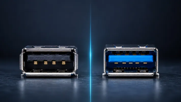
Quick Visual Guide
| Feature | USB 2.0 Type-A | USB 3.0 Type-A | USB 2.0 Micro-B | USB 3.0 Micro-B |
|---|---|---|---|---|
| Internal plastic color | Black or white | Blue | Black | Blue |
| Contact pins | 4 pins | 4 front + 5 rear = 9 pins | 5 pins | 10 pins (5 + 5 side extension) |
| Connector width | 12.0mm | 12.0mm | 6.85mm | 12.25mm (wider) |
| PCB footprint | 4-pad (V, D-, D+, G) | 9-pad | 5-pad | 10-pad |
| Key ID method | 4 visible contacts | Blue insert + extra pins visible deep inside | Standard micro shape | Wider body, blue insert |
1. The Pin Count Difference
USB 2.0 uses 4 contacts: VBUS (power), D- (data), D+ (data), GND (ground).
USB 3.0 adds 5 additional contacts for SuperSpeed signaling:
| Pin | USB 2.0 | USB 3.0 (adds) | Function |
|---|---|---|---|
| 1 (VBUS) | ✅ | — | +5V power |
| 2 (D-) | ✅ | — | Differential data (half-duplex) |
| 3 (D+) | ✅ | — | Differential data (half-duplex) |
| 4 (GND) | ✅ | — | Ground |
| 5 (SSRX-) | ❌ | ✅ | SuperSpeed receive (negative) |
| 6 (SSRX+) | ❌ | ✅ | SuperSpeed receive (positive) |
| 7 (GND_DRAIN) | ❌ | ✅ | Ground drain |
| 8 (SSPX-) | ❌ | ✅ | SuperSpeed transmit (negative) |
| 9 (SSPX+) | ❌ | ✅ | SuperSpeed transmit (positive) |
USB 3.0 is full-duplex: SSRX and SSPX operate independently (receive and transmit simultaneously). USB 2.0 D+/D- is half-duplex (send or receive, not both at once).
2. How to Tell Them Apart (Without a Multimeter)
Type-A Receptacle (Female / Panel Side)
- Look at the plastic insert color: Blue = USB 3.0. Black or white = USB 2.0. This is the USB-IF standard (not mandatory, but almost all manufacturers follow it).
- Look deep inside: If you see 5 extra contacts behind the 4 front contacts, it’s USB 3.0. USB 2.0 has only the 4 front contacts and empty space behind them.
- PCB side: USB 3.0 has 9 solder pads; USB 2.0 has 4.
Type-A Plug (Male / Cable Side)
- Look at the insert: Same blue = 3.0 rule.
- Look at the tongue: USB 3.0 plug has two rows of contacts on the tongue (5 rear + 4 front); USB 2.0 has one row (4 front).
- SS logo: USB 3.0 cables often (not generally) have “SS” (SuperSpeed) marking on the overmold.
Type-B (Printer / Scanner)
| Feature | USB 2.0 Type-B | USB 3.0 Type-B |
|---|---|---|
| Shape | Squarish, ~8mm | Rectangular with top bump, ~12mm tall |
| Pins | 4 | 9 |
| Compatibility | Plugs into 3.0 receptacle | Does NOT plug into 2.0 receptacle |
USB 3.0 Type-B is physically larger. A USB 3.0 Type-B cable cannot plug into a USB 2.0 Type-B device — it’s physically too big. However, a USB 2.0 Type-B cable CAN plug into a USB 3.0 Type-B receptacle (the top portion is the same as 2.0).
Micro-B (Phones, External Drives)
| Feature | USB 2.0 Micro-B | USB 3.0 Micro-B |
|---|---|---|
| Width | 6.85mm | 12.25mm (nearly double) |
| Pins | 5 | 10 (5 standard + 5 on side extension) |
| Visual | Standard micro shape | Wider with side extension |
USB 3.0 Micro-B is visually distinctive: it looks like a standard micro USB with a “sidecar.” Common on external hard drives (WD, Seagate). A USB 3.0 Micro-B cable can plug into a USB 2.0 Micro-B device (the sidecar overhangs, standard portion connects), but the reverse is not true.
Type-C
Type-C is the same physical connector for USB 2.0, 3.0, 3.1, 3.2, USB4, and Thunderbolt 3/4. The physical connector reveals nothing about the underlying protocol. Only the label, logo, or spec sheet tells you the actual speed.
3. PCB Footprint Comparison
| Parameter | Type-A USB 2.0 | Type-A USB 3.0 |
|---|---|---|
| Solder pads | 4 | 9 |
| Pad row spacing | Single row | 2 rows (4 front, 5 rear) |
| Total PCB footprint | ~14.5 × 7.0mm | ~14.5 × 10.5mm |
| Extra routing required | D+/D- pair only | D+/D- pair + SSRX pair + SSPX pair |
| Impedance control | 90Ω on D+/D- only | 90Ω on all three pairs |
| Recommended PCB layers | 2 layers | 4 layers (for controlled impedance on all pairs) |
USB 3.0 increases PCB design complexity significantly. Three differential pairs need controlled impedance routing. This is why many low-cost devices stay on USB 2.0 even when the SoC supports 3.0.
4. Backward Compatibility: What Plugs Into What
| Plug (Cable) | Receptacle (Device) | Works? | Speed |
|---|---|---|---|
| USB 2.0 Type-A | USB 3.0 Type-A | ✅ Yes | USB 2.0 (480Mbps) |
| USB 3.0 Type-A | USB 2.0 Type-A | ✅ Yes | USB 2.0 (480Mbps) |
| USB 2.0 Micro-B | USB 3.0 Micro-B | ✅ Yes (left half only) | USB 2.0 (480Mbps) |
| USB 3.0 Micro-B | USB 2.0 Micro-B | ❌ No (too wide) | — |
| USB 2.0 Type-B | USB 3.0 Type-B | ✅ Yes (top half only) | USB 2.0 (480Mbps) |
| USB 3.0 Type-B | USB 2.0 Type-B | ❌ No (too tall) | — |
| Type-C (any speed) | Type-C (any speed) | ✅ Yes | Negotiated |
Key rule: USB 2.0 plugs generally fit into USB 3.0 receptacles (at 2.0 speed). USB 3.0 plugs do NOT generally fit into 2.0 receptacles (they’re physically larger for Micro-B and Type-B).
5. Current Rating Difference
USB 2.0 and 3.0 connectors have different power delivery:
| USB Version | Base Current | After Negotiation | Max |
|---|---|---|---|
| USB 2.0 | 100mA (low-power), 500mA (high-power) | 500mA | 500mA |
| USB 3.0 | 150mA (low-power), 900mA (high-power) | 900mA | 900mA |
| USB 3.1+ with PD | 500mA–900mA | Negotiated via CC pin | 100W (5A at 20V) |
USB 3.0 Type-A connectors use thicker VBUS and GND contacts than USB 2.0, allowing higher current. This is visible in the connector: the outer two contacts (VBUS and GND) are slightly wider in USB 3.0.
6. When Does the Difference Actually Matter?
| Situation | USB 2.0 | USB 3.0 |
|---|---|---|
| Console / BMC port | ✅ Plenty (480Mbps for text console) | ❌ Overkill |
| Firmware update via flash drive | ✅ Plenty | ❌ Overkill |
| External SSD data transfer | ❌ 480Mbps bottlenecks | ✅ 5Gbps needed |
| Webcam / video capture | ❌ 480Mbps limits resolution | ✅ 5Gbps for 1080p60+ |
| Charging (5V) | 500mA max | 900mA max |
| Simple USB peripheral (mouse, keyboard) | ✅ Plenty | ❌ Overkill + higher cost |
Naming Note: USB 3.0, USB 3.1 Gen 1, and USB 3.2 Gen 1
Many buyers still say “USB 3.0,” but current product copy is clearer when it includes the speed class. In practical connector selection, “USB 3.0,” “USB 3.1 Gen 1,” and “USB 3.2 Gen 1” are commonly treated as 5Gbps-class SuperSpeed USB. For customer-facing pages, write the speed explicitly: USB 5Gbps, USB 10Gbps, USB 20Gbps, or USB4 40/80Gbps, depending on the actual implementation.
7. Common Mistakes
Mistake 1: Assuming blue = USB 3.0
Blue insert is a convention, not a requirement. Some manufacturers use black inserts on USB 3.0 connectors (cost saving, or for aesthetic reasons in black enclosures). Always check pin count on PCB side.
Mistake 2: Ordering USB 3.0 Micro-B cable for USB 2.0 device
USB 3.0 Micro-B male is 12.25mm wide. USB 2.0 Micro-B female is 6.85mm. It won’t fit. If your device has a standard micro USB port, order a USB 2.0 Micro-B cable.
Mistake 3: Routing USB 3.0 on 2-layer PCB
3 differential pairs need controlled impedance. 2-layer PCB ground planes are unreliable for 90Ω control. Use 4-layer minimum for USB 3.0.
Mistake 4: USB 3.0 for 10cm trace = same as USB 2.0 for 10cm
USB 3.0 signals contain frequency components up to 2.5 GHz. At these frequencies, even 5cm of uncontrolled trace causes significant insertion loss. USB 2.0 (480 Mbps, 240 MHz component) is far more forgiving.
GSConn manufactures USB 2.0 and USB 3.0 connectors in Type-A, Type-B, Micro-B, and Type-C form factors. Standard through-hole and SMT mounting, industrial temperature options available. Color inserts conform to USB-IF convention: black for 2.0, blue for 3.0. Custom colors available for branding.
Related reading:
– USB 3.2 Gen 1 vs Gen 2 vs Gen 2×2
– USB Connector Signal Integrity
– USB Type-C Pinout & Wiring Diagram
Technical References for Editorial Review
This article was reviewed for engineering accuracy against commonly used connector and USB ecosystem references, including USB-IF Type-C / USB4 / USB Power Delivery documentation, IEC 60512 connector test methods, EIA-364 test methods, and representative connector manufacturer datasheets. Always verify final dimensions, plating thickness, reflow limits, and durability ratings against the exact connector datasheet before releasing a design.