
Board-to-Board Connector Mating Cycles: Durability and Life Expectancy
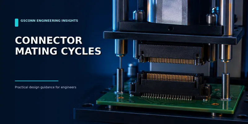
Board-to-Board Connector Mating Cycles: Durability and Life Expectancy
A mating-cycle rating states how many complete insertions and withdrawals a connector has passed under defined test conditions. It does not guarantee the same life in a dusty service bay, a vibrating vehicle or a misaligned test fixture.
The useful engineering question is not simply “How many cycles?” It is: What changed after those cycles, under which conditions, and did the connector still meet the electrical and mechanical limits that matter to the application?
Short answer: Use the supplier’s qualified cycle rating for the exact plug, receptacle, plating, stack height and test sequence. Then add application-specific exposure—such as vibration, humidity, contamination or off-axis handling—when the field environment is more severe than the catalog test.
What a mating-cycle rating should include
| Item | What to request |
|---|---|
| Mated pair | Exact plug and receptacle part numbers |
| Finish | Contact-zone plating system and thickness |
| Cycle count | Number of complete mate/unmate operations |
| Test method | Standard, speed, alignment and conditioning |
| Electrical result | Initial and final contact resistance |
| Mechanical result | Insertion/withdrawal or retention force |
| Visual result | Wear, exposed underplate, cracks or deformation |
| Environment | Temperature, humidity and any preconditioning |
Without these details, two “500-cycle” claims may not represent comparable performance.
1. What IEC 60512-9-1 does—and does not—define
IEC 60512-9-1, test 9a, provides a standardized method for assessing mechanical operational endurance in normal connector operation without electrical load. It creates a consistent test framework.
The standard does not create one universal cycle count or pass/fail resistance limit for every connector. Those requirements are set by the relevant detail specification, product specification or test plan.
A robust validation plan normally measures:
- Low-level contact resistance before and after cycling
- Insertion and withdrawal force at defined intervals
- Contact retention and housing condition
- Latch, key and alignment-feature function
- Evidence of plating wear or exposed base material
- Intermittent discontinuity, where required
- Signal-integrity change for high-speed connectors
2. The main contact-wear mechanisms
Each mating operation creates controlled wiping between contact surfaces. Wipe helps break through films and contaminants, but it also removes a small amount of finish.
The wear rate depends on:
- Contact geometry and wipe distance
- Normal force and local contact pressure
- Surface roughness
- Gold or other final-finish thickness
- Nickel underplate and base material
- Lubrication
- Debris removal or accumulation
- Alignment and insertion angle
Once the protective finish is worn through, the exposed underplate or base metal can oxidize or corrode. Contact resistance may then become less stable, particularly at low signal levels.
3. Gold vs tin: avoid oversimplified cycle rules
Gold is commonly preferred for repeated mating because it resists oxidation and supports stable low-level contact performance. Tin can be appropriate for cost-sensitive or low-cycle applications, but its behavior depends heavily on contact force, wipe, fretting and environment.
| Finish choice | Typical reason to use it | Questions to ask |
|---|---|---|
| Tin | Low cost, limited service, suitable normal-force/wipe design | Fretting risk? Cycle qualification? Mixed-finish compatibility? |
| Gold flash | Corrosion protection for low-cycle applications | Is the finish thick enough for the required wear? |
| Selective gold over nickel | Repeated mating and stable low-level signals | Thickness in the actual contact zone? Porosity? |
| Heavy precious-metal system | High-cycle fixtures or harsh reliability targets | Is the contact geometry also rated for the cycle count? |
Plating thickness alone cannot predict cycle life. A heavier finish usually increases wear margin, but spring fatigue, latch damage, debris and misalignment may become the limiting failure modes.
Unit check: Connector gold thickness may be stated in microinches (µin) or micrometres (µm). They are not interchangeable: 1 µin = 0.0254 µm. Always preserve the unit shown on the supplier drawing.
4. Mechanical failures can occur before electrical failure
| Failure mode | Typical cause | What the user experiences |
|---|---|---|
| Reduced socket normal force | Spring stress relaxation or overstress | Intermittent contact or low retention |
| Bent or pushed-back contact | Misalignment or inadequate retention | No connection on one circuit |
| Housing crack | Side load, poor guidance or material damage | Loose or impossible mating |
| Latch fatigue | Repeated over-deflection | Cable or board pair disconnects |
| Floating mechanism damage | Debris, overtravel or constrained mounting | Loss of alignment compensation |
| Solder-joint fatigue | Connector used as a structural locator | Intermittent board-level failure |
For serviceable equipment, the inspection plan should include both electrical measurements and mechanical checks.
5. Why field life can be shorter
Laboratory cycling usually controls alignment, speed and cleanliness. Field use may add:
- Side load from cables or board leverage
- Angular mating
- Dust, fibers or process residue
- Humidity and corrosive atmospheres
- Vibration-induced micromotion
- ESD or hot-plug arcing
- Mating with damaged or contaminated contacts
Fretting is especially important. Very small relative motion can disrupt protective films and generate wear debris even when the connector is not intentionally unmated.
6. Build a realistic qualification sequence
For a serviceable industrial connector, a useful sequence might be:
- Record baseline contact resistance and mating force.
- Apply the intended number of controlled mating cycles.
- Repeat electrical and mechanical measurements.
- Expose samples to the relevant temperature/humidity or vibration profile.
- Repeat measurements and inspect the contact zone.
- Test latch/keying function and look for pushed-back contacts.
- For high-speed links, compare S-parameters or channel margin before and after.
Do not combine stresses arbitrarily and label the result an “acceleration factor.” Temperature, dust and vibration can introduce different failure mechanisms, so simple multipliers rarely provide a defensible life prediction without a validated model.
7. Design practices that improve service life
- Select a finish and contact geometry qualified for the target cycle count.
- Use housings with adequate lead-in and polarization.
- Prevent the PCB or cable from applying side load during unmating.
- Keep connectors covered or protected during manufacturing and service.
- Specify cleaning methods compatible with the resin, finish and lubricant.
- Use manufacturer-approved lubricant only; uncontrolled products can trap debris or attack plastics.
- Make high-cycle wear parts replaceable where practical.
- Provide a defined insertion/removal tool for dense or high-force connectors.
- Avoid using the connector as the only structural support between boards.
8. What to put in the RFQ
Include:
- Target number of mating cycles and expected cycles per day/month
- Manual, robotic or blind-mate operation
- Acceptable insertion/withdrawal force
- Contact-resistance limit and measurement method
- Voltage/current or signal interface
- Plating system and thickness units
- Temperature, humidity, dust and chemical exposure
- Vibration/shock requirements
- Latch/keying requirements
- Inspection and replacement strategy
This converts “long life” into a testable specification.
FAQ
Is 500 mating cycles enough?
It may be ample for a product opened only during scheduled maintenance and inadequate for a daily test fixture. Convert the service profile into lifetime operations, then add environmental and misuse margin.
Does thicker gold always mean more cycles?
It generally increases wear reserve, but it does not fix poor contact geometry, side loading, spring fatigue or housing damage. Review the qualification data for the complete mated pair.
Can a connector still fail with low contact resistance?
Yes. A broken latch, cracked housing, pushed-back contact or loss of normal force may make the connector unusable even if a static resistance measurement passes.
Should I cycle the connector under electrical load?
IEC 60512-9-1 addresses mechanical operation without electrical load. Hot-plug or current-breaking applications require additional tests and a connector designed for that duty.
Request durability data
Send GSConn the connector geometry, required cycles, environment, electrical load and service method. Ask for the exact mated-pair qualification report, plating specification and post-cycle acceptance criteria before approving a high-cycle application.
Sources and further reading
- https://webstore.iec.ch/en/publication/2410
- https://webstore.iec.ch/en/publication/2365
- https://webstore.iec.ch/en/publication/2328
Related guides: b2b-pin-header-female-header-guide.md · b2b-connector-materials-guide.md · b2b-connector-selection-guide.md
Related reading on GSConn
- Wire-to-Board vs Board-to-Board Connectors
- Industrial USB Connector Guide
- IP67 vs IP68 USB Connector
- Stacked USB Connector Guide
- Request a Quote
Engineering references
- Product drawing, datasheet, material declaration and qualification report for the selected connector series
- IPC land-pattern and acceptability guidance applicable to the PCB assembly class
- Project-specific vibration, shock, thermal and electrical requirements