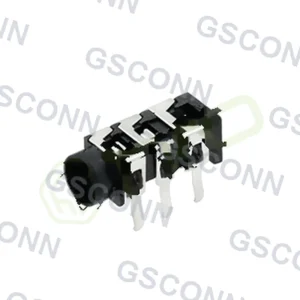
Mid-Mount vs Panel-Mount Audio Jacks: Load Paths and Solder Joint Fatigue

Where the insertion force goes
Every time a plug goes into a jack, a force of several newtons is applied along the plug axis. That force has to go somewhere. Where it goes determines which part of the product fails first.
A panel-mount jack sends it into the enclosure. A PCB-mounted jack sends it into the solder joints. A mid-mount jack sends it into the board edge and the pads around a cutout. Three mounting styles, three different load paths, three different fatigue mechanisms.
This article traces the load path in each case and identifies when mechanical support is mandatory rather than optional.
The three mounting styles
| Style | How it mounts | Primary load path | Barrel position |
|---|---|---|---|
| Panel mount | Body fixed to the enclosure with a nut or screws | Enclosure wall | Through the panel |
| PCB mount, top entry | Pins or pads on the board, barrel above the board | Solder joints | Above the PCB |
| Mid-mount | Body sits in a cutout in the board edge | Board edge and surrounding pads | Flush with the board edge |
The mid-mount variant exists so the barrel can reach the enclosure wall without a separate panel part. That convenience is exactly what puts the load into the board.
The load path in detail
Consider a horizontal insertion force F applied to the plug. The jack reacts at its mounting points, and the moment arm is the distance from the plug axis to those points.
| Mounting | Where the force is reacted | Moment arm | What fatigues |
|---|---|---|---|
| Panel mount | Panel boss and nut | Short, through the panel | The panel feature, not the electronics |
| PCB top entry | Solder joints under the body | The height of the barrel above the board | Solder joints and pads |
| Mid-mount | Pads at the board edge | Distance from the plug axis to the nearest pads | Board edge pads, and sometimes the laminate |
The moment arm is the key quantity. A tall jack on a thin board has a long moment arm and small pads. That is the worst combination, and it is common.
Why solder joints fail and how to recognise it
A cracked solder joint on an audio jack does not usually fail open. It goes intermittent, and it responds to pressure.
| Symptom | What it indicates | How to confirm |
|---|---|---|
| Audio cuts out when the cable is moved | Joint or pad cracking | Flex the board near the jack while monitoring continuity |
| Audio returns when the board is pressed | Classic cracked joint | Same test, with pressure applied deliberately |
| One channel only | Crack at that channel’s pad | Inspect the specific joint under magnification |
| Works cold, fails warm | Differential expansion opening a crack | Thermal cycle while monitoring |
| Fails after handling, then recovers | Mechanical, not electrical | Tap test |
The “works when pressed” signature is so characteristic that it should be a documented diagnostic step, not something discovered after three replacement boards.
When mid-mount is the right answer
Mid-mount is chosen for thin products where the jack barrel must sit flush with the case edge without a separate panel component. It is a legitimate choice, but it comes with conditions.
| Condition | Requirement |
|---|---|
| Board edge cutout | Cutout tolerance must match the jack body, or the body is stressed |
| Mechanical support | The board must be supported behind the jack, or the edge flexes |
| Pad design | Larger pads and, where possible, through-hole anchors |
| Enclosure interface | The case must constrain the jack body, not just surround it |
| Assembly sequence | The jack must be placed before the board is constrained, or it cannot be seated |
The last row is a manufacturing constraint that catches teams late. A mid-mount jack that must be installed from the board edge cannot be added after the board is screwed down.
Adding support without changing the jack
If a PCB-mounted jack is already specified and the application involves repeated insertion, support can be added externally.
| Measure | Effect | Cost |
|---|---|---|
| Chassis rib behind the jack | Takes the load off the pads | Tooling change on the enclosure |
| Bracket or clip | Transfers force to the chassis | Extra part and assembly step |
| Through-hole anchor pins | Stronger than SMT pads alone | Requires a jack with anchors |
| Stiffener on the board | Reduces board flex under load | Board space and cost |
| Adhesive or potting | Distributes load | Rework difficulty; not for serviceable parts |
The bracket is usually the most practical for an existing design. A small formed metal part that captures the jack body and screws to the chassis converts a pad-loaded joint into a chassis-loaded one.
Insertion force and cycle count together
Fatigue depends on both. A high force applied a few times is harmless; a moderate force applied thousands of times is not.
| Insertion force | 50 cycles | 500 cycles | 5,000 cycles |
|---|---|---|---|
| Low (~5 N) | Fine | Fine | Inspect joints |
| Moderate (~10 N) | Fine | Inspect joints | Support required |
| High (~20 N) | Inspect joints | Support required | Panel mount only |
The table is a guide, not a specification. The point is that “how many times will this be plugged in” is as important as “how hard is it to plug in,” and both are usually estimated poorly.
Panel mount: what to watch
Panel mount solves the solder joint problem and moves the risk to the enclosure.
| Risk | Cause | Mitigation |
|---|---|---|
| Panel cracking | Thin wall, repeated load | Boss or reinforcing rib around the hole |
| Nut loosening | Vibration | Thread locker or a locking nut |
| Gasket compression loss | Thermal cycling, over-torque | Specified torque and a resilient gasket |
| Wire fatigue | Repeated flexing at the solder cup | Strain relief and a service loop |
The wire fatigue point is specific to panel-mount jacks with solder cups or flying leads. The jack is fixed and the harness moves, so the flex point is right at the termination. A service loop and a tie-down prevent it.
Decision table
| Application | Recommended mounting | Support needed |
|---|---|---|
| Plugged once at installation | PCB SMT | None |
| Plugged occasionally, indoors | PCB through-hole | None if the board is rigid |
| Plugged regularly | PCB through-hole plus bracket | Yes |
| Vibrating panel, field serviceable | Panel mount | Panel boss |
| Thin product, flush barrel | Mid-mount | Board support behind the jack |
| Washdown enclosure | Panel mount, sealed | Sealing is the constraint |
FAQ
Why does my audio come back when I press on the board? A cracked solder joint or pad on the jack. The mechanical pressure temporarily restores contact. It is the classic signature of a load-path failure.
Is mid-mount weaker than top-mount? It puts the load into the board edge rather than under the body, so it needs support behind the jack. With support it is fine; without it, the edge flexes.
How many insertion cycles should a PCB jack withstand? Depends on force and support. A few hundred with moderate force is usually fine on a rigid board; thousands require a bracket or panel mount.
Can I add support after the design is done? Yes, with a bracket that captures the jack and screws to the chassis. That is usually the cheapest retrofit.
Does a through-hole jack eliminate the problem? It reduces it substantially, because the pins carry load in shear rather than the pads in peel. It does not eliminate it if the board itself flexes.
What is the most common panel-mount failure? Wire fatigue at the solder cup, because the jack is fixed and the harness moves. Add a service loop and a tie-down.
Audio Connectors for this design
View all 134 parts →