
Pluggable Terminal Block Selection and Application Guide
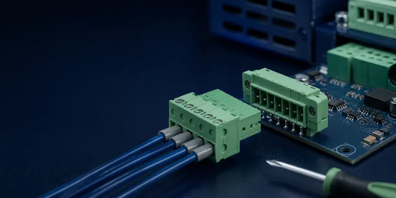
A pluggable terminal block separates field wiring from the PCB through a removable plug-and-header interface. It can shorten installation time, simplify module replacement and allow harnesses to be prewired away from the final assembly. The design still needs careful attention to pitch, coding, retention, touch safety, mating direction and the current rating of the complete mated pair.
Typical Pitch Ranges
These values are early-selection ranges. The exact current, conductor size, voltage and pole count depend on the complete plug/header combination and its approval.
| Pitch | Current (IEC) | Wire Range | Positions | Best For |
|---|---|---|---|---|
| 3.5mm | 8A | 0.14–1.5mm² | 2–24 | Signal, sensors, compact |
| 5.0mm | 12A | 0.2–2.5mm² | 2–24 | General industrial |
| 5.08mm | 12–16A | 0.2–2.5mm² | 2–24 | UL standard, worldwide |
| 7.5mm | 16A | 0.2–4mm² | 2–12 | Power connections |
| 7.62mm | 16A | 0.2–4mm² | 2–12 | UL standard, power |
| 10.16mm | 20A+ | 0.5–6mm² | 2–8 | High current |
1. What Is a Pluggable Terminal Block?
A pluggable terminal block is a two-piece connector system: a fixed base soldered to the PCB, and a removable plug where wires are terminated. The plug can be disconnected from the base without removing individual wires.
[PCB] ←solder→ [Base (female)] ←mate/unmate→ [Plug (male)] ←wire entry→ [Field wiring]During installation or service, a technician can disconnect the plug while the field conductors remain terminated. This is especially useful for replaceable control modules and preassembled harnesses. The circuit must still be de-energized unless the connector is specifically rated and the procedure allows live mating.
Conventional Terminal (Fixed) vs Pluggable
| Fixed Terminal | Pluggable Terminal | |
|---|---|---|
| Wire removal for service | Unscrew each wire individually | Unplug the entire block (wires stay in plug) |
| Field replacement | Rewire entire connector | Swap plug assembly, base stays on PCB |
| Pre-wiring | At final assembly only | Harness can be pre-wired off-site |
| Mating cycles | N/A (wires are torqued) | 50–200 |
| Cost | Lower | 1.5–2× fixed terminal |
2. Wiring Types on the Plug Side
| Wire Entry | Description | Best Use |
|---|---|---|
| Top entry (vertical) | Wire enters from top, parallel to PCB surface | Standard, most common |
| Side entry (horizontal) | Wire enters from side, parallel to PCB | Low-profile enclosures |
| 45° entry | Angled entry, compromise between top and side | Tight above-PCB clearance |
| Dual entry | Top + side wire entry on same plug | Layout flexibility |
3. Locking and Retention
Pluggable terminal blocks need retention to prevent accidental disconnection:
| Retention Type | Force | Vibration Rating | Release |
|---|---|---|---|
| Friction fit | Low | Poor — not for vibration | Pull straight |
| Locking flange | Medium | Good | Release tab |
| Screw flange | High | Excellent | Unscrew flange, pull |
| Latch | Medium-high | Good | Press tab, pull |
For vibration or high pull-out risk, positive retention such as a screw flange or latch is often preferred. Select the mechanism using the supplier’s vibration data, required service access and available panel space.
4. Coding / Keying
Pluggable terminals can be mechanically keyed to prevent inserting the wrong plug into the wrong base. Plastic coding pins are inserted into slots in the plug and base:
- Coding pin position A: Only mates with base position A
- Coding pin position B: Only mates with base position B
This is particularly valuable when one PCB has several identical-looking connectors serving different functions, such as 24V power and analog I/O. Mechanical coding reduces mis-mating risk, while clear circuit labeling and different pole counts or colors can provide additional error-proofing.
5. PCB and Enclosure Checks Designers Often Miss
- Confirm the plug can be inserted and removed without colliding with the enclosure, adjacent connectors or cable duct.
- Provide enough board support for mating and unmating forces; large connectors may need flanges or chassis support.
- Verify the pin layout, drill size, soldering process and copper area for the intended current.
- Check creepage and clearance at the wire entry, between adjacent poles and on the PCB.
- Define whether the header is male or female and whether live parts remain finger-accessible when unmated.
- Check wire bend radius and strain relief so cable force is not transferred directly to the solder joints.
- Specify coding, color and labels in the bill of materials—not as an installation afterthought.
6. Selection Checklist
- Circuit current, voltage and required approval.
- Solid, stranded or ferruled conductor range.
- Pitch, number of positions and PCB orientation.
- Screw, spring or push-in wire connection.
- Required mating cycles and maintenance interval.
- Friction, latch or screw-flange retention.
- Coding and touch-safety requirements.
- Header mounting, solder profile and board support.
Common Questions
Can plugs and headers from different series be mixed?
Do not assume compatibility from pitch alone. Keying, pin geometry, polarization, contact plating and approval conditions can differ. Use a qualified mating pair from the same documented system.
Is a 5.08mm connector always rated higher than a 5.0mm connector?
No. Pitch influences spacing, but current depends on contact design, conductor size, pole count, temperature and approval. Compare exact part numbers.
How many mating cycles are enough?
For factory assembly, a modest cycle rating may be sufficient. Frequently serviced modules need a higher declared durability and a defined inspection/replacement plan.
7. GSConn Pluggable Series
| Series | Pitch | Current | Wire Entry | Features |
|---|---|---|---|---|
| TB-PL-350 | 3.5mm | 8A | Top | Compact signal |
| TB-PL-508 | 5.08mm | 12A | Top / Side / 45° | Universal, screw or spring wire clamp |
| TB-PL-762 | 7.62mm | 16A | Top | Power, up to 4mm² |
| TB-PL-508-F | 5.08mm | 12A | Top | Screw flange for vibration |
| TB-PL-508-K | 5.08mm | 12A | Top | Keying pins included |
Configure the Right Mating Pair
GSConn offers pluggable terminal families in multiple pitches, wire-entry directions and retention styles. Ask for a matched plug/header recommendation with the required conductor range, mating cycles, coding and approval data; confirm exact ratings in the series datasheet.
Related reading: