
Mezzanine Connector Selection: Pitch, Stack Height and Alignment
Mezzanine Connector Selection: Pitch, Stack Height and Alignment
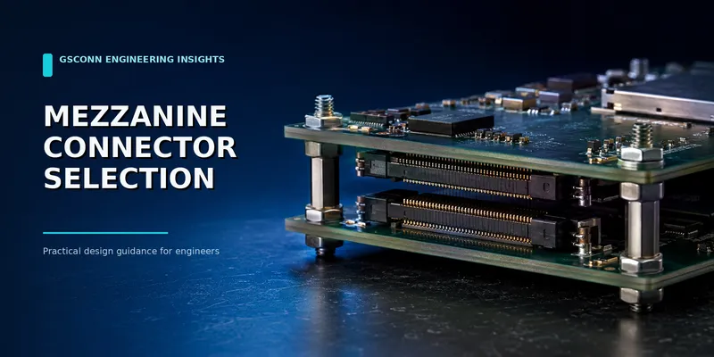
A mezzanine connector joins two parallel PCBs with a plug and receptacle. It can deliver high circuit density and a repeatable board-to-board distance in a much smaller volume than a conventional 2.54 mm header.
That precision creates its own design constraints. Pitch, mated height, capture range, PCB bow, placement accuracy and signal launch must be evaluated as one mechanical-electrical system.
Short answer: Choose the lowest pitch only after confirming that your PCB fabricator and assembler can hold the required footprint, coplanarity and placement tolerances. Define the mated stack height and complete tolerance stack before selecting the plug/receptacle pair.
Quick selection framework
| Requirement | Design direction | Main verification |
|---|---|---|
| Minimum PCB area | Finer pitch, more rows | Routing escape and assembly yield |
| Very low board spacing | Low-profile matched pair | Component keep-out and PCB bow |
| Multiple height options | One family with several plug/receptacle heights | Valid combinations in manufacturer matrix |
| Blind mating | Guided or floating connector | Capture range and chassis alignment |
| High-speed differential links | Characterized high-speed mezzanine | S-parameters and PCB launch |
| Power + signals | Hybrid or allocated parallel contacts | Current-temperature derating |
| Frequent service | Higher-durability family and mechanical support | Mating-cycle qualification |
1. Define mated stack height
The critical dimension is normally the distance between the facing PCB surfaces after the connector is fully mated. Depending on the family, the final height may be set by:
- One fixed plug and several receptacle heights
- Several plug/receptacle combinations
- A connector pair with a permitted mating-height range
Use the manufacturer’s mating-combination table. Do not calculate stack height by adding visible housing dimensions unless the drawing explicitly instructs you to do so.
The mechanical stack should include:
- Nominal mated height
- Connector-height tolerances
- PCB thickness and flatness
- Mounting standoff tolerance
- Enclosure and chassis tolerance
- Component height on facing PCB surfaces
- Required air gap, insulation or thermal pad
2. Pitch controls more than density
Finer pitch can reduce area, but it also changes:
- Pad width and solder-mask strategy
- Escape routing and via technology
- Placement accuracy
- Coplanarity sensitivity
- Inspection method
- Repairability
- Allowable contamination
| Design priority | Typical pitch direction |
|---|---|
| Wearable/mobile size | 0.35–0.5 mm families |
| Compact embedded module | 0.4–0.8 mm families |
| Industrial robustness and easier routing | 0.8–1.27 mm families |
These ranges describe common market options, not a performance rating. A 0.8 mm connector may outperform a 0.5 mm connector at high speed if its contact and ground architecture is better characterized.
3. Position count and pin-map architecture
Allocate circuits before choosing the housing:
- Power and return
- Ground shields
- Differential pairs
- Low-speed controls
- Detect/enable pins
- Reserved positions
For high-speed designs, a ground-signal pattern may consume substantially more positions than the logical interface count. For power, parallel contacts need a thermally and electrically balanced PCB connection.
Leave space for pin-map revisions. Moving a differential pair late in layout may require a different escape strategy or break the validated connector pin pattern.
4. Alignment, capture range and floating options
Rigid fine-pitch mezzanine connectors typically tolerate only limited lateral and angular error. Determine who locates the boards:
| Assembly architecture | Connector implication |
|---|---|
| One PCB mounted, second guided directly onto it | Standard guided mezzanine may work |
| Both PCBs fixed independently to chassis | Floating connector or compliant mounting is often safer |
| Blind-mate field replacement | Lead-in, keying and hard stops are important |
| Large or flexible boards | Multiple connectors require careful positional tolerance |
Do not use the connector as the primary hard stop unless the product is designed for that load. Standoffs or chassis features should control final board position without over-compressing the connector.
5. SMT assembly requirements
Fine-pitch mezzanine connectors are commonly supplied in tape-and-reel with a pick-and-place cap. The process should address:
- Footprint and solder-mask definition
- Stencil thickness and aperture reduction
- Paste type and printing stability
- Placement accuracy and connector coplanarity
- Reflow profile and housing-grade compatibility
- AOI access and hidden-joint limitations
- Board support during reflow
- Rework plan
Long connector housings can magnify PCB warpage and coplanarity error. Use production-representative panelization and thermal mass during process qualification.
6. Signal-integrity evaluation
For multi-gigabit links, request the exact connector model:
- Differential and common-mode S-parameters
- Insertion/return loss and crosstalk
- Reference-plane and de-embedding information
- Tested stack height
- Recommended footprint and breakout
- Validated signal/ground pin map
The same connector family may perform differently at different mated heights or pin assignments. Simulate the connector together with PCB pads, vias and traces.
7. Current and thermal design
Per-contact current varies by contact geometry, loaded positions, ambient temperature and PCB copper. If the mezzanine carries both power and signals:
- Separate heat-generating power contacts from sensitive lanes where possible
- Balance power and return locations
- Use the exact mated-pair derating data
- Consider dedicated power contacts or a second connector
- Test temperature rise in the final enclosure
Fine pitch and high density reduce cooling space, so a large number of nominally rated contacts may still need aggressive derating.
8. Example: Raspberry Pi Compute Module 4
The Raspberry Pi Compute Module 4 uses two 100-pin high-density connectors to connect the module to a carrier board. It is a useful illustration of how a mezzanine pair can carry power, low-speed control and high-speed interfaces in a compact form.
The lesson is not to copy its connector blindly. Use the official CM4 datasheet, mating connector details and recommended footprint because the dual-connector spacing and mechanical alignment are part of the system.
9. Mezzanine vs pin header
| Factor | Mezzanine connector | Pin/female header |
|---|---|---|
| Density | High | Low to moderate |
| Low stack height | Strong | Limited |
| Height precision | Defined by matched pair | Depends on selected pin/socket geometry |
| High-speed options | Many characterized families | Only when specifically designed/characterized |
| Assembly | Fine-pitch SMT common | Through-hole and SMT options |
| Prototyping/rework | More difficult | Easier |
| Cost | Higher | Lower |
| Alignment tolerance | Often limited; guided/floating options available | Usually forgiving at coarse pitch but pins can bend |
10. RFQ checklist
- Board orientation and mechanical drawing
- Pitch and position count
- Required mated stack height and tolerance
- Plug/receptacle mounting orientation
- Maximum X/Y/angular misalignment
- Standard, guided or floating architecture
- Current and number of loaded contacts
- Signal interfaces and impedance target
- Mating-cycle requirement
- Operating environment
- SMT process limits and packaging
- Annual volume and prototype date
FAQ
Is a smaller pitch always better?
No. It saves space but can increase routing, assembly and inspection difficulty. Select the largest pitch that meets density and performance needs unless product architecture requires otherwise.
Can I mix plug and receptacle heights from the same family?
Only combinations approved by the manufacturer. Similar-looking parts may not provide the intended engagement or stack height.
When do I need a floating mezzanine connector?
When chassis and board tolerances exceed the rigid connector’s capture range, when boards are mounted independently, or when vibration would otherwise transfer stress to solder joints.
Can mezzanine connectors carry PCIe?
Some can. Verify the exact connector, stack height, pin map and channel model for the required PCIe generation.
Request a stack-height review
Send GSConn the mechanical stack-up, PCB outlines, position count, signal interfaces, power requirement and alignment tolerance. Ask for a valid plug/receptacle combination and both recommended footprints before layout begins.
Sources and further reading
- https://pip.raspberrypi.com/documents/RP-008168-DS-cm4-datasheet.pdf
- https://www.molex.com/en-us/products/connectors/board-to-board-connectors/slimstack-connectors
- https://webstore.iec.ch/en/publication/2410
Related guides: b2b-connector-selection-guide.md · b2b-high-speed-connector-guide.md · b2b-connector-materials-guide.md
Related reading on GSConn
- Wire-to-Board vs Board-to-Board Connectors
- Industrial USB Connector Guide
- IP67 vs IP68 USB Connector
- Stacked USB Connector Guide
- Request a Quote
Engineering references
- Product drawing, datasheet, material declaration and qualification report for the selected connector series
- IPC land-pattern and acceptability guidance applicable to the PCB assembly class
- Project-specific vibration, shock, thermal and electrical requirements